| Columns Retired Columns & Blogs |
The Waveform Loudspeaker Measurements
Sidebar 1: Measurements
Footnote 1: See pp.166–167 in the October 1989 issue for a full discussion of how and why I test loudspeakers in-room.—John Atkinson
As Larry said earlier, we ran a couple of FFT response measurements on the Waveforms while John Ötvös was visiting, in order to check that the speakers were working okay, and found that the speaker had an excess of energy in the top audio octave. According to John, the reason for adding the ribbon supertweeter to a tweeter that is usually used alone (a version of Dynaudio's D28) is to fill in a suckout in the high treble on the intended listening axis. After Larry had completed his listening, I ran a more rigorous set of tests to investigate the Waveform's measured performance further.
First, I looked at the speaker's spatially averaged room response on a 1/3-octave basis (footnote 1), fundamentally examining the Waveform's forward response in a window centered on the listening seat (fig.1). (The match between the woofer and the upper range of the speaker was achieved with the bass level set to "–3" and the bass contour set to "4," which was how Larry had been listening using the VTLs on the top and the Krell KSA-200 on the bass.) Points to note are the smoothness of the response trend from 200Hz or so to the upper presence region, around 6kHz. The crossovers between the subwoofer and midwoofers and between the latter and the dome tweeter have obviously been well-managed, and the sound should be smoother overall throughout the midrange than the Mirage M-1 which so excited LA in the June issue, which has a slight boost in the middle mids. ("Middle mids!" Oh English language, where are you when I need you?)
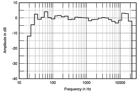
Fig.1 Waveform Loudspeaker, spatially averaged, 1/3-octave response in LA's listening room.
Second, the near-corner room placement excites room resonances to a greater degree than placing the speakers further out in the room. Despite the spatial averaging, which usually "smooths out" the effects of room modes in this measurement, the Waveform can be seen to boost the 32Hz and 63Hz 1/3-octave bands to a significant degree. Due to the close positioning of the subwoofer to the floor and the highish crossover to the midwoofers, the normal floor dip in the 200–300Hz range has been pushed up in frequency and reduced in amplitude, there only being a slight lack of energy in the 315Hz and 400Hz 1/3-octave bands. The LF extension in-room, however, is good, the speaker not reaching its half-power point until a low 23Hz or so. This was confirmed by the nearfield measurement of the woofer response, the –6dB point again lying at 23Hz (without taking the port contribution into account).
The main response anomaly, however, can be seen in the treble, where a general lack of energy in the upper presence region, which would contribute to Larry's feeling that the speaker lacked immediacy, is followed by a significant energy peak in the 12.5kHz and 16kHz bands. This peak was noticeable on all forward axes and is exacerbated both at high levels, as the region immediately beneath it then depresses even further (this also shown in Waveform's own measurements), and if the listener's ears are much above the dustcap of the upper of the two mid-woofers. This peak won't be perceived as a "brightness," being too high in frequency, but will noticeably "whiten" recorded hiss and, as Larry says above, also makes the speakers very intolerant of any source that also has problems in the treble. It could be plainly heard as a distinctly metallic-sounding "whistle" on pink noise.
Looking at the individual response curves taken to derive fig.1 suggests that the smoothest integration across the treble region (though still with too much HF energy audible) is with the listener's ears about 27" off the ground. This is an unrealistically low listening height, however; in my experience, 32" to 39" is more typical.
Laterally, however, the individual measurements taken for fig.1 suggest a wide listening window over which the spectral balance stays quite uniform, without any "hot seat" effect.
Fig.2 shows the Waveform's response to a 25µs rectangular pulse on an axis 36" off the floor, ie, level with the upper of the two woofers, which is where Larry's listening chair placed my ears. With a horizontal scale of two large divisions equal to 1ms, the impulse response is not at all time-coincident, due to the use of steep-slope crossovers. The impulse shape clearly suggests multiple arrival times for the contributions from the many drivers. The impulse tail is also overlaid with a degree of HF ringing.
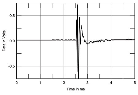
Fig.2 Waveform Loudspeaker, impulse response on axis 36" from floor (5ms time window).
The speaker's anechoic response, derived by FFT analysis from five impulse measurements taken across a ±15° horizontal window, is shown in fig.3 along with the subwoofer's nearfield measured response. The boost in the top octave is clearly visible, as is a ragged-shaped suckout in the octave below. The position, width, and depth of this suckout are all extremely dependent on the measuring axis; in fact, moving the microphone a little higher and further back than the position used to derive figs.2 and 3 gave a narrow notch 16dB deep at a hair above the crossover frequency, 9kHz! This axis sensitivity of the upper treble balance is undoubtedly due to the use of two widely spaced drivers in this region, something that is rarely seen. In general, designers wanting to use a supertweeter place it very close to the main tweeter—the Spendor BC1, for example—in order to minimize such problems.
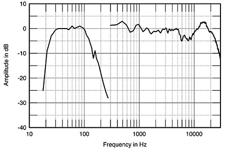
Fig.3 Waveform Loudspeaker, FFT-derived quasi-anechoic response, averaged across 30° horizontal window on axis 36" from the floor, corrected for microphone response, plus nearfield response of subwoofer.
Fig.3 also suggests a slight degree of midrange emphasis to the sound, agreeing with the overall in-room response trend in fig.1. Looking at the nearfield response of the subwoofer in fig.3, you can see a small peak at 157Hz. This was due to a high-Q resonance centered on this frequency and could be clearly heard as a "hoot" as the sinewave swept through its position. I suspect that this may have something to do with Larry's feeling that there was an audible anomaly in this region, particularly as the resonance's highish-Q nature—its –3dB points were just 9Hz on either side—suggests that it will not always be excited by music.
The phase and amplitude of the Waveform's two sections are shown in figs.4 (upper range) and 5 (subwoofer). The midwoofers feature a high impedance which should not prove to be any problem; though the dome and ribbon tweeters do drop to 4 ohms and slightly below, this is with a negligible phase angle throughout their passband. Fig.5 reveals the presence of the woofer resonance, with small kinks in both phase and amplitude plots at approximately 160Hz. The port tuning is revealed by the amplitude minimum just above 20Hz, while the overall characteristic suggests that the Waveform's bass driver is an easy amplifier load overall.

Fig.4 Waveform Loudspeaker, midrange/HF section, electrical impedance (solid) and phase (dashed) (2 ohms/vertical div.).

Fig.5 Waveform Loudspeaker, subwoofer section, electrical impedance (solid) and phase (dashed) (2 ohms/vertical div.).
Finally, I looked at the Waveform's electronic crossover characteristics. The crossover circuitry and all the in/out sockets are carried on one large printed-circuit board, with a small transformer supplying AC power to a pair of solid-state voltage regulators. All the filter circuits are based on Signetic NE5532 dual-op-amp ICs, and the response-shaping networks are carried on plug-in DIP headers to allow for easy modifications. Good-quality components are used throughout, including Bourns pots for the two controls, but the unit as a whole would seem a little outclassed by the amplification the Waveform speakers are likely to be used with, in my opinion.
Yes, the sound of a circuit using op-amps will be dependent to a large extent on the way in which the designer has implemented the power supplies and other ancillary matters, as well as by the characteristics of the particular IC used. However, it is fair to point out that the 5532 is some 10 years old and there are a number of op-amp ICs now available that offer significant improvements in both subjective and objective performance. That LA felt the Waveforms to have overall a rather non-involving nature could well be due to the crossover circuitry, I feel.
I found that the "bass level" control altered the gain in the low-pass channels by a dB amount approximately equal to the numbers engraved on the front panel, from –9dB to +15dB, while the "bass contour" control affected the amount of boost applied centered on 29Hz. In fig.6, the highest of the LF curves was taken with the control set to "0," with the other three "4," "7," and "10," the latter slightly cutting the subwoofer's overall level in the low bass. The rest of fig.6 shows the equalization applied by the crossover box to the high-pass feeds, which consists of a slight peaking of the midwoofer response—+1.5dB at 225Hz—coupled with a deliberate boost applied to the range covered by the supertweeter—+4dB at 16kHz. This goes a long way toward explaining the HF boost noted both in the listening tests and in my in-room measurements. I have to say that either the supertweeter or the boost alone applied to the dome tweeter would each have been sufficient to ensure a flat treble response. With both, however, the result is, to my ears, unlistenable.—John Atkinson
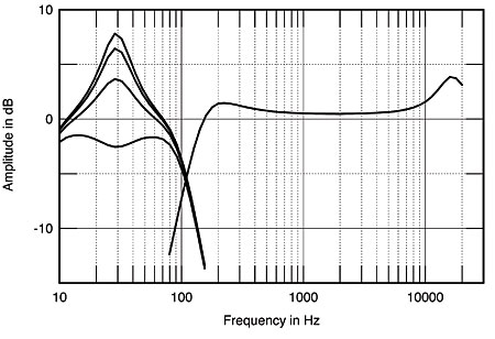
Fig.6 Waveform Loudspeaker electronic crossover, high-pass (right) and low-pass (left) functions. The latter are with the Bass Contour set to (from top to bottom): "0," "4," "7," and "10."
Footnote 1: See pp.166–167 in the October 1989 issue for a full discussion of how and why I test loudspeakers in-room.—John Atkinson
NEXT: Manufacturer's Comment »
|
| ||||||||||
- Log in or register to post comments


| Loudspeakers Amplification Digital Sources | Analog Sources Accessories Featured | Music Columns Retired Columns | Show Reports | Features Latest News Community | Resources Subscriptions |
 © 2024 Stereophile
AVTech Media Americas Inc., USA
All rights reserved

