| Columns Retired Columns & Blogs |
VTL TL-5.5 Series II Signature line preamplifier Measurements
Sidebar 3: Measurements
I measured the TL-5.5 Series II Signature's electrical performance with Stereophile's loan sample of the top-of-the-line Audio Precision SYS2722 system (see www.ap.com and the January 2008 "As We See It," ). No phono stage was fitted. I made sure that the VTL's inputs were correctly set for balanced (blue LED illuminated) or unbalanced (green LED illuminated) operation. As used by Bob Reina, the two toggle switches inside the TL-5.5 II, one for each channel, were set to Low Gain. The maximum gain for balanced input, balanced output with the volume control set to its maximum of "117" was 9.4dB, which is slightly less than the 11dB specified for the VTL's Low Gain mode. The maximum single-ended input/output gain was 6dB lower, as expected, at 3.4dB. With the switches set to Normal Gain, the maximum gain was now 17.5dB for balanced and 11.5dB for single-ended operation, both figures 0.5dB higher than specified. Other than the very top step, from "116" to "117," the volume control operated in accurate 0.5dB steps.
At low and middle frequencies, the single-ended input impedance was almost to spec, at 33k ohms, dropping inconsequentially to 29k ohms at the top of the audioband. The balanced impedance was the same for each signal phase, meaning that it was twice the single-ended impedance overall. All inputs preserved absolute polarity (ie, were non-inverting) with the red Phase LED off. The VTL's output impedance was slightly higher than the specified 150 ohms, at 200 ohms single-ended and 376 ohms balanced in the midrange and above. The audible difference between the specified and measured impedances will be inconsequential. By 20Hz the impedance had risen to 273 ohms single-ended and 576 ohms balanced, presumably due to the presence of output coupling capacitors. As a result, when the TL-5.5 II was used to drive the very low 600 ohm test load (fig.1, cyan and magenta traces), the low frequencies rolled off below 50Hz to reach –3dB at 14Hz. Into the high 100k ohms load (fig.1, blue and red traces) the response was flat in the audioband, and down by just 0.5dB at 200kHz. Note, also, the superb channel matching in this graph. Commendably, the frequency response was unaffected by the volume-control setting.
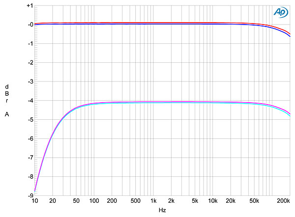
Fig.1 VTL TL-5.5 II, balanced frequency response with volume control set to "117" at 1V, into: 100k ohms (left channel blue, right red), 600 ohms (left cyan, magenta right) (1dB/vertical div.).
Channel separation (not shown) was excellent at >100dB below 1kHz, but decreased to 76dB in both directions at 20kHz. The unweighted, wideband signal/noise ratio, ref. 1V output with the input shorted and the volume control set to "117," was 76.3dB left and 79dB right, which are good if not great. These figures improved to 98.8 and 104.2dB, respectively, when an A-weighting filter was switched into circuit. Fig.2 reveals a little more random noise in the left channel (blue trace), though the right channel also shows some very low-level harmonics of the supply frequency.
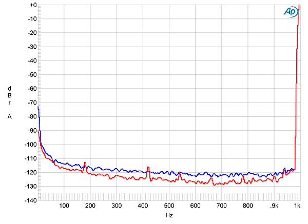
Fig.2 VTL TL-5.5 II, balanced spectrum of 1kHz sinewave, DC–1kHz, at 2V into 100k ohms (left channel blue, right red; linear frequency scale).
Fig.3 plots the percentage of THD+noise against the balanced output voltage into 100k ohms in Low Gain mode. The rising trend below 1.5V suggests that the distortion is buried below the noise at these output levels. (The noise, being constant in level, becomes an increasingly large percentage of the output voltage as the latter decreases.) The distortion rises above 2V output, but the TL-5.5 II doesn't actually clip until the output reaches 20V—more than five times the voltage required to drive power amplifiers into clipping. The balanced output clips at 1.2V into 60 ohms (not shown), strongly suggesting that the TL-5.5 II not be used with loads that low. Fig.4 is a similar analysis performed from the single-ended output into 10k ohms, probably the lowest impedance the VTL would see in practical use. The distortion is a little higher, though not to any extent that would cause alarm, and the output now clips at 6.2V. This is still higher than would ever be required to drive a power amplifier into clipping.
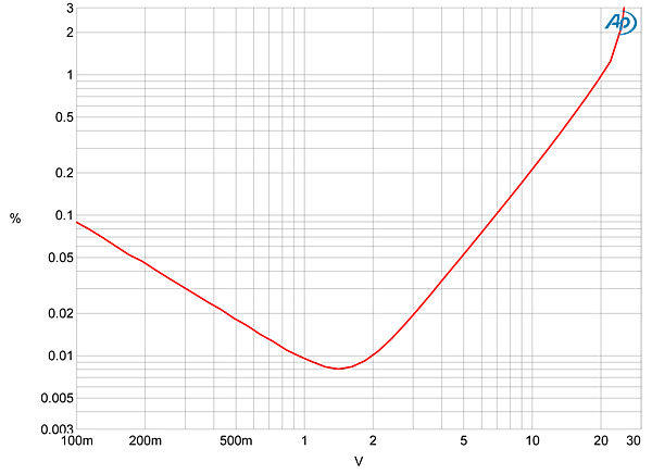
Fig.3 VTL TL-5.5 II, balanced distortion (%) vs 1kHz output voltage into 100k ohms.
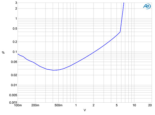
Fig.4 VTL TL-5.5 II, unbalanced distortion (%) vs 1kHz output voltage into 10k ohms.
That the TL-5.5 II is incompatible with low impedances is confirmed by fig.5, which shows that while the THD+N percentage in the balanced output doesn't change with frequency into 100k ohms, and is very low, at <0.01%, it rises to almost 1% into 600 ohms. The distortion itself comprises almost entirely the subjectively innocuous second and third harmonics into high impedances (fig.6), and intermodulation distortion is similarly low (fig.7)—although this graph, too, shows the slightly higher level of noise in the left channel.

Fig.5 VTL TL-5.5 II, balanced THD+N (%) vs frequency at 1V into: 100k ohms (left channel blue, right red), 600 ohms (left cyan, right magenta).
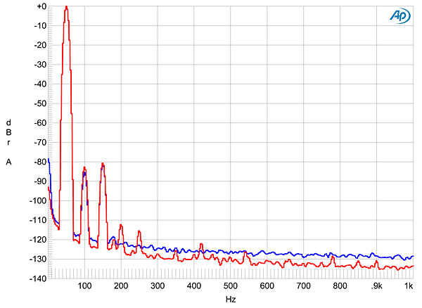
Fig.6 VTL TL-5.5 II, balanced spectrum of 50Hz sinewave, DC–1kHz, at 2V into 100k ohms (left channel blue, right red; linear frequency scale).
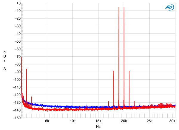
Fig.7 VTL TL-5.5 II, balanced HF intermodulation spectrum, DC–30kHz, 19+20kHz at 2V peak into 100k ohms (left channel blue, right red; linear frequency scale).
VTL's TL-5.5 Series II Signature is a nicely engineered preamplifier that offers no measured compromise resulting from its use of tubes, other than its inability to drive unrealistically low load impedances.—John Atkinson
|
|
| ||||||||||
- Log in or register to post comments


| Loudspeakers Amplification Digital Sources | Analog Sources Accessories Featured | Music Columns Retired Columns | Show Reports | Features Latest News Community | Resources Subscriptions |
 © 2024 Stereophile
AVTech Media Americas Inc., USA
All rights reserved

