| Columns Retired Columns & Blogs |
VTL Siegfried Series II Reference monoblock power amplifier Measurements
Sidebar 3: Measurements
VTL's Siegfried Series II Reference has both balanced and single-ended inputs and can be operated in tetrode or triode output-stage modes, each with four levels of negative feedback. Because fully characterizing its performance in every one of the 16 possible conditions would be very time consuming, I performed a limited set of measurements in all 16, and then a more complete set using the balanced input and in both triode and tetrode modes, each with minimum and maximum feedback—which VTL respectively calls Low Damping Factor (LDF) and Max Damping Factor (MDF). I used my top-of-the-line Audio Precision SYS2722 system (see www.ap.com and the January 2008 "As We See It").
The Siegfried II's balanced and unbalanced inputs both preserved absolute polarity (ie, were non-inverting) with the rear-panel Phase switch set to "0," and offered the same voltage gain. In triode mode (red LED illuminated), the gain ranged from 30.1dB with MDF to 33.8dB with LDF. Gain in tetrode mode (green LED) was a little higher, at 31.7dB/MDF and 36.5dB/LDF. The balanced input impedance was a usefully high 90k ohms at low and middle frequencies, dropping to a still-high 76k ohms at 20kHz. As expected, the singled-ended input impedances were half the balanced figures.
With its dozen 6550 output tubes, the Siegfried II's output impedance was low for a tubed design. The lowest impedance was in triode/MDF mode, at 0.88 ohm in the midband and 0.9 ohm at the extremes of the audioband. As a result, the variation in the amplifier's frequency response due to the interaction of this impedance with that of our standard simulated loudspeaker remained within ±0.5dB limits (fig.1, gray trace). This graph also indicates that the Siegfried II rolls off cleanly above the audioband, reaching –3dB at 130kHz into 8 ohms (blue trace). The output impedance rose a little with each reduction of feedback, reaching 1.36 ohms at 1kHz and 1.4 ohms at the frequency extremes in the LDF condition, when the response variation was ±1dB and the HF rolloff was now –3dB at 80kHz (fig.2). The output impedance in tetrode mode was only slightly higher than in triode mode, varying from 0.9 ohms at 1kHz/MDF to 1.53 ohms 1kHz/LDF. The variations in response with our simulated loudspeaker were therefore of the same order (fig.3, gray trace), but the ultrasonic response was more extended in tetrode mode, with the –3dB point into 8 ohms varying from >200kHz/MDF (fig.3, blue) to 150kHz/LDF.
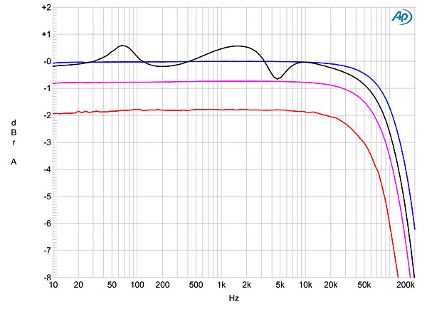
Fig.1 VTL Siegfried II Reference, triode/MDF, frequency response at 2.83V into: simulated loudspeaker load (gray), 8 ohms (blue), 4 ohms (magenta), 2 ohms (red) (1dB/vertical div.).
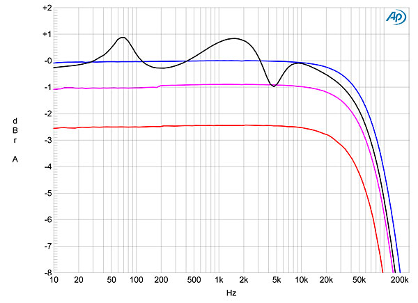
Fig.2 VTL Siegfried II Reference, triode/LDF, frequency response at 2.83V into: simulated loudspeaker load (gray), 8 ohms (blue), 4 ohms (magenta), 2 ohms (red) (1dB/vertical div.).
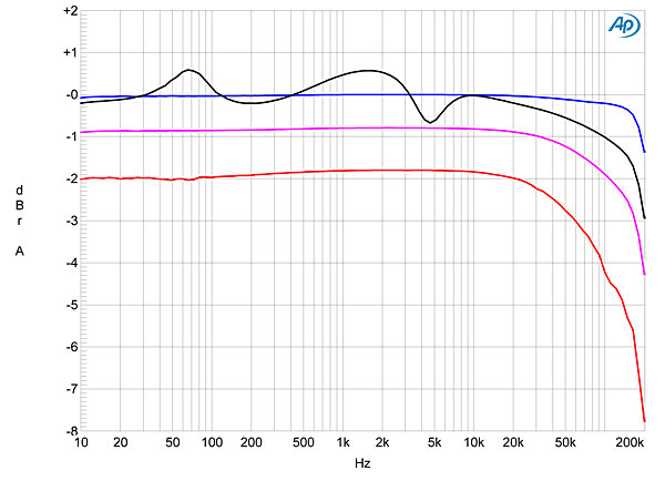
Fig.3 VTL Siegfried II Reference, tetrode/MDF, frequency response at 2.83V into: simulated loudspeaker load (gray), 8 ohms (blue), 4 ohms (magenta), 2 ohms (red) (1dB/vertical div.).
Perhaps more important, in tetrode/MDF, the ultrasonic rolloff has a sharper corner that correlates with the small degree of overshoot and damped oscillation in the Siegfried II's reproduction of a 10kHz squarewave in this condition (fig.4). For comparison, fig.5 shows the VTL's reproduction of the 10kHz squarewave in triode/LDF. The waveform is superbly square, with no incipient instability, and the 1kHz squarewave in this mode is essentially perfect (fig.6). These last two graphs are a testament to the quality of the Siegfried's output transformer.
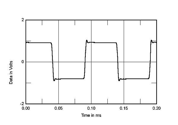
Fig.4 VTL Siegfried II Reference, tetrode/MDF, small-signal 10kHz squarewave into 8 ohms.
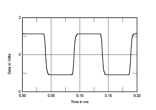
Fig.5 VTL Siegfried II Reference, triode/LDF, small-signal 10kHz squarewave into 8 ohms.
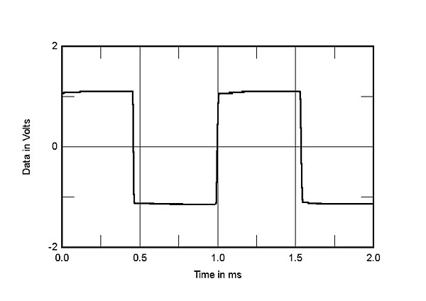
Fig.6 VTL Siegfried II Reference, triode/LDF, small-signal 1kHz squarewave into 8 ohms.
With its high gain, even with MDF, the Siegfried II is not the quietest high-power amplifier I have measured. The unweighted wideband signal/noise ratio, measured with the input shorted and ref. 1W into 8 ohms, varied from 75.4dB in tetrode/LDF to 81.7dB in triode/LDF. Restricting the measurement bandwidth to the audioband improved these ratios by a couple of dB, while switching in an A-weighting filter gave ratios of 83.2dB in tetrode/LDF, 85.3dB in triode/LDF, 87.9dB in tetrode/MDF, and 89.5dB in triode/MDF. Spectral analysis of the amplifier's low-frequency noise floor (fig.7) indicated that the primary source of noise was magnetic interference from the AC transformer at 60Hz and its odd-order harmonics, though it's fair to note that even the highest-level component, at 180Hz, is still down by 85dB from the 1W output level and will not be audible.
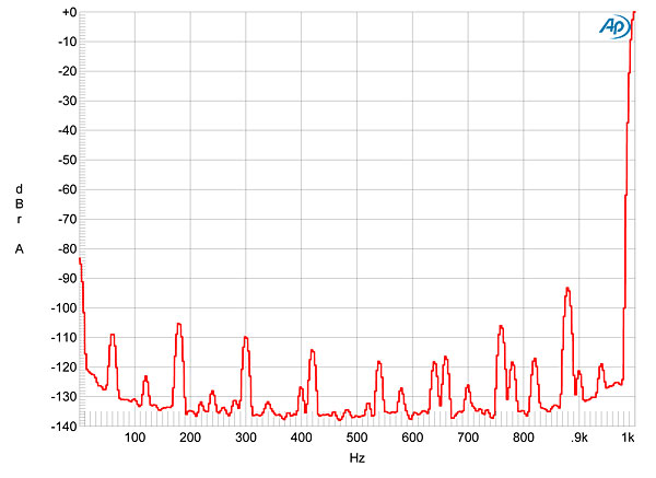
Fig.7 VTL Siegfried II Reference, spectrum of 1kHz sinewave, DC–1kHz, at 1W into 8 ohms (linear frequency scale).
VTL specifies their amplifiers' rated powers into 5 ohms, which is awkward for reviewers: our test loads come in multiples of 4 ohms. I therefore measured the Siegfried II's maximum power into 4 and 8 ohms in tetrode and triode modes, each with LDF and MDF. The clipping power (defined as when the THD+noise reaches 1%) wasn't affected by the amount of feedback, though the percentage of THD was a little higher below clipping with LDF. Fig.8 shows how the THD+N varies with output power into 8 ohms with the Siegfried II set to triode/LDF. The distortion is very low at low powers, starts to rise above the noise floor above a few hundred milliwatts, remains less than 0.1% below 25W, and reaches 1% at 250W (24.0dBW). Fig.9 shows the 4 ohm behavior, again in triode/LDF. The amplifier now clips at 315W (21.9dBW), but the distortion is still respectably low at lower powers. Fig.10 shows the Siegfried II's behavior into 8 ohms in tetrode/LDF. The low-power distortion is even lower than in triode mode, and the amplifier now clips at 425W (26.3dBW). Into 4 ohms in tetrode mode (fig.11), the Siegfried clipped at 600W (24.7dBW).
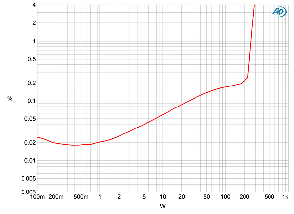
Fig.8 VTL Siegfried II Reference, triode/LDF, distortion (%) vs 1kHz continuous output power into 8 ohms.
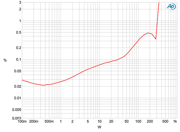
Fig.9 VTL Siegfried II Reference, triode/LDF, distortion (%) vs 1kHz continuous output power into 4 ohms.
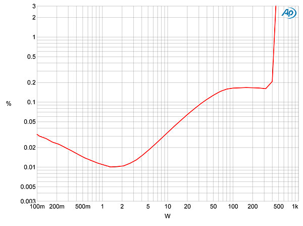
Fig.10 VTL Siegfried II Reference, tetrode/LDF, distortion (%) vs 1kHz continuous output power into 8 ohms.
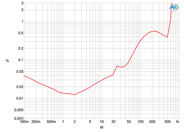
Fig.11 VTL Siegfried II Reference, tetrode/LDF, distortion (%) vs 1kHz continuous output power into 4 ohms.
Figs. 12 and 13 show how the percentage of THD+N varies with frequency into 8, 4, and 2 ohms at a level where I could be sure I was looking at actual distortion rather than noise. Fig.12 shows the behavior in triode/LDF, fig.13 in tetrode/LDF. The 8 ohm distortion (blue traces) was low in both modes, with tetrode slightly lower overall. There is also only a slight rise in THD toward the top of the audioband. But as the load impedance drops, the THD rises overall, and the increase at high frequencies rises further. Comparing these two graphs, and looking at the graphs taken with MDF (not shown), suggests that while the Siegfried II offers the lowest measured distortion in tetrode/MDF, the amplifier deals better with low impedances in triode mode, at all DF settings.
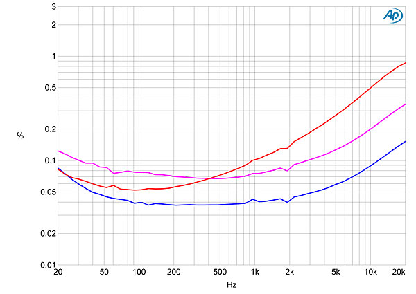
Fig.12 VTL Siegfried II Reference, triode/LDF, THD+N (%) vs frequency at 6.34V into: 8 ohms (blue), 4 ohms (magenta), 2 ohms (red).
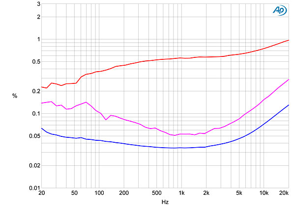
Fig.13 VTL Siegfried II Reference, tetrode/LDF, THD+N (%) vs frequency at 9V into: 8 ohms (blue), 4 ohms (magenta), 2 ohms (red).
Also to be considered is the fact that, in triode mode, the distortion in the midrange is primarily the subjectively innocuous second harmonic (fig.14), while in tetrode mode some higher-order harmonics appear (fig.15). The differences are more pronounced at low frequencies and higher powers. In triode mode (fig.16), the second and third harmonics are equally strong, at –60dB (0.1%) each, while in tetrode mode (fig.17) the third and fifth harmonics are strongest, at, respectively, –52dB (0.25%) and –68dB (0.04%).
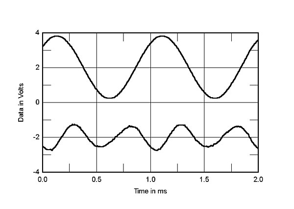
Fig.14 VTL Siegfried II Reference, triode/LDF, 1kHz waveform at 1.3W into 8 ohms, 0.024% THD+N (top); distortion and noise waveform with fundamental notched out (bottom, not to scale).
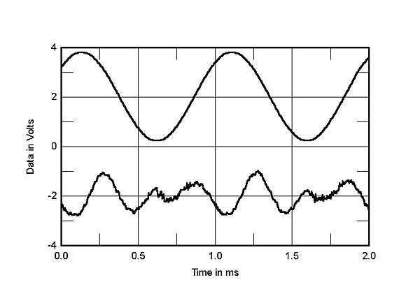
Fig.15 VTL Siegfried II Reference, tetrode/LDF, 1kHz waveform at 2W into 8 ohms, 0.011% THD+N (top); distortion and noise waveform with fundamental notched out (bottom, not to scale).
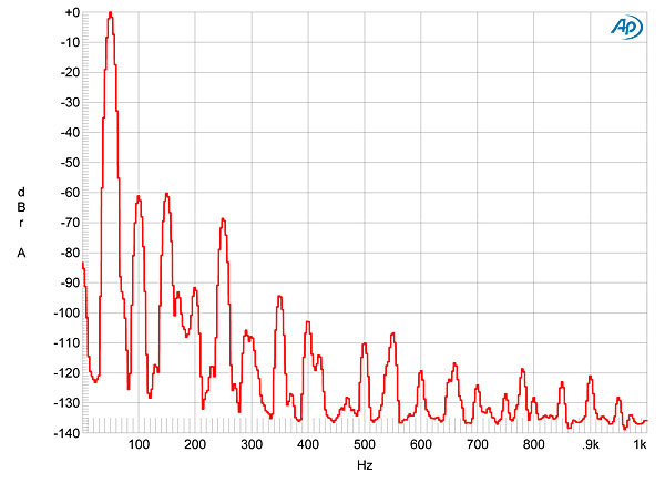
Fig.16 VTL Siegfried II Reference, triode/LDF, spectrum of 50Hz sinewave, DC–1kHz, at 100W into 8 ohms (linear frequency scale).
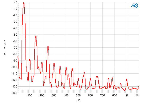
Fig.17 VTL Siegfried II Reference, tetrode/LDF, spectrum of 50Hz sinewave, DC–1kHz, at 1W into 8 ohms (linear frequency scale).
Despite its decreasing linearity at high frequencies and at high powers, the Siegfried II performed relatively well when tested with an equal mix of 19 and 20kHz tones at a level a few dB below visual clipping on an oscilloscope. Fig.18 was taken in triode/LDF into 4 ohms, which was the worst case. Even so, the 1kHz difference component lies at –53dB (0.25%), and the higher-order products, at 18 and 21kHz, are a couple of dB lower in level.
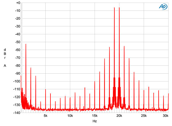
Fig.18 VTL Siegfried II Reference, triode/LDF, HF intermodulation spectrum, DC–30kHz, 19+20kHz at 100W peak into 4 ohms (linear frequency scale).
VTL's Siegfried Series II Reference is large and massive, and its measured performance shows that it is, indeed, a powerhouse. Even with its negative feedback set to its minimum, the amplifier still offers low levels of distortion at the kinds of power levels likely to be seen in practice. Though the best linearity is to be obtained in tetrode mode, the spectral signature of the distortion and the way in which the amplifier's behavior changes with decreasing load impedance suggests that triode mode will be preferred.—John Atkinson
|
|
| ||||||||||
- Log in or register to post comments


| Loudspeakers Amplification Digital Sources | Analog Sources Accessories Featured | Music Columns Retired Columns | Show Reports | Features Latest News Community | Resources Subscriptions |
 © 2024 Stereophile
AVTech Media Americas Inc., USA
All rights reserved

