| Columns Retired Columns & Blogs |
VTL S-400 Reference power amplifier Measurements
Sidebar 3: Measurements
For logistical reasons, I measured a different sample of the S-400 to the one BD auditioned. My sample had been used at the Home Entertainment Show last May and came to me following the Show, before its return to New York dealer Sound By Singer.
With its choices of unbalanced and balanced inputs, and triode or tetrode output-stage operation, VTL's S-400 is four amplifiers in one. To make measuring its performance feasible, I carried out complete sets of tests for both triode and tetrode operation in balanced mode, spot-checking some measurements via the unbalanced input. All the inputs preserved absolute polarity, the XLRs appearing to be wired with pin 2 hot.
Before I did many tests, the amplifier was run for an hour at one-third power in tetrode mode into 8 ohms. The voltage gain into 8 ohms was the same with both balanced and unbalanced drive, but differed between the two output modes: tetrode was 27.2dB, triode lower at 25.3dB. The unbalanced input impedance was a moderately high 74.2k ohms at 1kHz, dropping at the frequency extremes to 56k ohms (20Hz) and 44.4k ohms (20kHz). As expected, the balanced input impedances were twice these figures. The S-400 should not load down the output of any preamplifier with which it is used.
The output impedance also differed between the two operating modes, ranging from 1.82 ohms at 1kHz to 1.9 ohms at 20Hz and 20kHz in tetrode mode, and from 1.66 ohms at 1kHz to 1.7 ohms at the frequency extremes in triode mode. As a result of the Ohm's Law interaction between this source impedance and the manner in which a loudspeaker's impedance changes with frequency, there was a significant, ±0.6dB modification of the amplifier's frequency response by the magazine's simulated speaker in both modes (fig.1, tetrode; fig.2, triode). Note the more extended ultrasonic bandwidth of tetrode compared with triode in these graphs: –3dB at 115kHz vs –3dB at 87kHz, respectively. (The unbalanced responses were identical.) Both bandwidths are more than is necessary to handle audio signals, but correlate with superb reproduction of a 10kHz squarewave (fig.3, tetrode; fig.4, triode). However, tetrode mode reveals some damped overshoot on the squarewave's leading edges, this increasing in level into higher impedances.
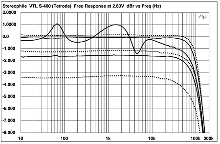
Fig.1 VTL S-400, tetrode mode, balanced frequency response at 2.83V into (from top to bottom at 2kHz): simulated loudspeaker load, 8, 4, 2 ohms (1dB/vertical div., right channel dashed).
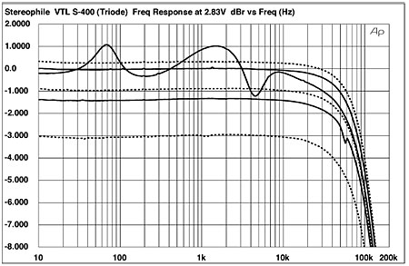
Fig.2 VTL S-400, triode mode, balanced frequency response at 2.83V into (from top to bottom at 2kHz): simulated loudspeaker load, 8, 4, 2 ohms (1dB/vertical div., right channel dashed).
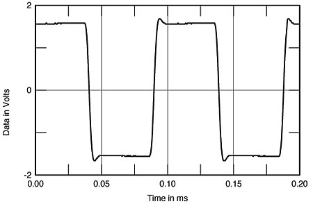
Fig.3 VTL S-400, tetrode mode, small-signal 1kHz squarewave into 8 ohms.
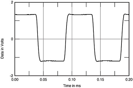
Fig.4 VTL S-400, triode mode, small-signal 1kHz squarewave into 8 ohms.
Channel separation (not shown) was better than 90dB in the midrange, decreasing slightly at the top of the audioband. Background noise levels were low, with the A-weighted signal/noise ratio (ref. 1W into 8 ohms) measuring 91.4dB in tetrode mode, 89.3dB in triode. The wideband, unweighted figures were still good, at 78.4dB and 80.2dB, respectively.
Figs.5 and 6 plot the THD+noise percentage present in the S-400's output against output power into 8, 4, and 2 ohm loads, for tetrode and triode operation, respectively. As is usual with an amplifier featuring low loop negative feedback, the distortion rises linearly with increasing power. We usually assess an amplifier's maximum power when the distortion in its output reaches 1%, but as shown by figs.5 and 6, the S-400's power delivery is limited when this criterion is applied. VTL specifies the amplifier's power at a more relaxed 3% THD+N, and at this level the S-400 gave out 325W (25.1dBW) into 8 ohms in tetrode mode, 200W (23dBW) in triode mode. Into 4 ohms, the maximum powers available were 405W (23.1dBW) and 220W (20.4dBW), respectively.
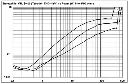
Fig.5 VTL S-400, tetrode mode, distortion (%) vs 1kHz continuous output power into (from bottom to top at 1W): 8, 4, 2 ohms.
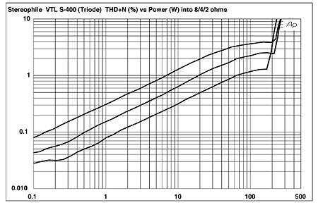
Fig.6 VTL S-400, triode mode, distortion (%) vs 1kHz continuous output power into (from bottom to top at 1W): 8, 4, 2 ohms.
The amplifier works very hard into 2 ohms, however, with 220W available in tetrode mode (17.4dBW) and 200W in triode mode (17dBW). (VTL specifies the S-400's optimal load as 5 ohms.) This is also revealed by the plots of the S-400's small-signal THD+noise against frequency (fig.7, tetrode; fig.8, triode), where the 2 ohm performance is less good than that into higher impedances. However, the VTL's small-signal distortion is heavily second- and third-harmonic in nature (fig.9, tetrode; fig.10, triode), which will be subjectively innocuous, especially at the low static levels featured in these graphs.
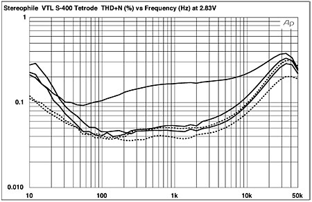
Fig.7 VTL S-400, tetrode mode, THD+N (%) vs frequency at 2.83V into (from bottom to top): 8, 4, 2 ohms.
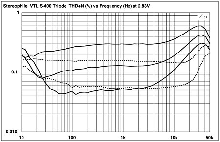
Fig.8 VTL S-400, triode mode, THD+N (%) vs frequency at 2.83V into (from bottom to top): 8, 4, 2 ohms.
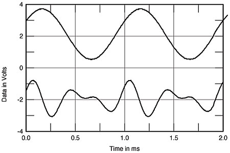
Fig.9 VTL S-400, tetrode mode, 1kHz waveform at 1.5W into 4 ohms (top), 0.098% THD+N; distortion and noise waveform with fundamental notched out (bottom, not to scale).
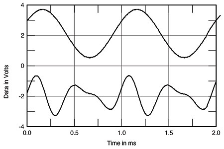
Fig.10 VTL S-400, triode mode, 1kHz waveform at 1.05W into 4 ohms (top), 0.107% THD+N; distortion and noise waveform with fundamental notched out (bottom, not to scale).
At high powers, the S-400's low loop feedback means that higher-order harmonics make an appearance (fig.11, tetrode; fig.12, triode), though the fact that the harmonics decrease linearly in level with increasing order works against their audibility, especially in triode mode. (Note the commendable absence of power-supply–related spuriae in these graphs.) The big VTL did less well when it came to high-power intermodulation testing (fig.13, tetrode; fig.14, triode; both taken just below visible waveform clipping on the oscilloscope screen), which is what I expected from the decreasing linearity shown at high frequencies in the THD plots (figs.7 and 8).
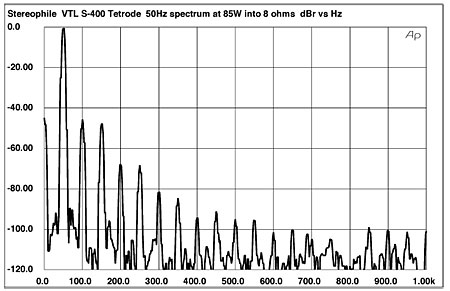
Fig.11 VTL S-400, tetrode mode, spectrum of 50Hz sinewave, DC–1kHz, at 85W into 8 ohms (linear frequency scale).
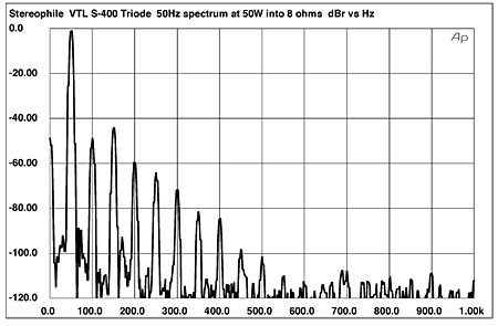
Fig.12 VTL S-400, triode mode, spectrum of 50Hz sinewave, DC–1kHz, at 50W into 8 ohms (linear frequency scale).
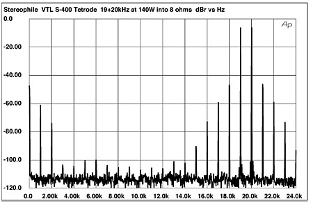
Fig.13 VTL S-400, tetrode mode, HF intermodulation spectrum, DC–24kHz, 19+20kHz at 140W peak into 8 ohms (linear frequency scale).
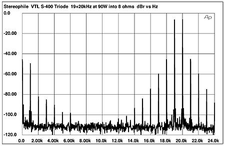
Fig.14 VTL S-400, triode mode, HF intermodulation spectrum, DC–24kHz, 19+20kHz at 90W peak into 8 ohms (linear frequency scale).
VTL's S-400 is a thoroughly worked-out tube design whose computer-monitored operating conditions should ensure many years of service. Its designer's decision to go for low levels of loop negative feedback does compromise the amplifier's high-power linearity, but the tradeoff is probably the very low levels of static distortion when the amplifier is giving out less than 10W. Even so, it is probably best to avoid speakers that plunge much below 4 ohms to get the maximum dynamic range from this amplifier, even though I note that BD had no problems driving his Thiel CS6es, which remain between 2.5 ohms and 4 ohms over most of the audioband.—John Atkinson
|
|
| ||||||||||
- Log in or register to post comments


| Loudspeakers Amplification Digital Sources | Analog Sources Accessories Featured | Music Columns Retired Columns | Show Reports | Features Latest News Community | Resources Subscriptions |
 © 2024 Stereophile
AVTech Media Americas Inc., USA
All rights reserved

