| Columns Retired Columns & Blogs |
Theta Digital Intrepid 5-channel power amplifier Measurements
Sidebar 3: Measurements
Following the usual one-hour preconditioning period at one-third power into 8 ohms with all channels driven, the Theta Intrepid's casework was very warm, but not so hot that I couldn't keep my hand on it. Its input impedance was a fairly high 54k ohms via the unbalanced input, slightly less than double this figure via the balanced XLR jack. Voltage gain into 8 ohms was a slightly low 24.6dB from either input—as with the Citadel, which was reviewed in the May Stereophile, I didn't find the balanced input to offer the usual 6dB increase in gain—and the amplifier preserved absolute polarity.
The source impedance was on the high side for a solid-state design, at 0.65 ohm. This resulted in ±0.5dB variations in frequency response with our standard simulated loudspeaker (fig.1, top dotted trace), and about a 0.6dB reduction in level each time the load impedance halved (fig.1, lower traces). A slight, 0.1dB imbalance can be seen between the two channels plotted in this graph. Fig.2 shows the responses of all five channels: the maximum imbalance is 0.25dB. These responses were all measured using the unbalanced inputs; no difference was seen from the balanced inputs. The Intrepid's ultrasonic output is rolled off by just 1.5dB at 200kHz, meaning that the waveform of a 10kHz squarewave (fig.3) shows very little slowdown of its risetime. There is also a slight hint of overshoot evident.
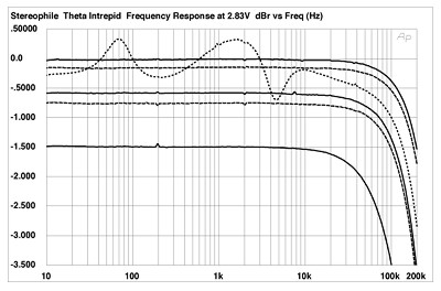
Fig.1 Theta Intrepid, channel 1 frequency response at (from top to bottom at 2kHz): 2.83V into dummy loudspeaker load, 1W into 8 ohms, 2W into 4 ohms, 4W into 2 ohms (channel 2 dashed, 0.5dB/vertical div.).

Fig.2 Theta Intrepid, channels 1 and 3 frequency responses at 1W into 8 ohms (channels 2, 4, and 5 dashed, 0.5dB/vertical div.).
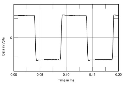
Fig.3 Theta Intrepid, small-signal 10kHz squarewave into 8 ohms.
To look at channel separation, I drove the right-hand channel's input and measured the bleedthrough into each of the other four channel outputs (I shorted their inputs). To my surprise, given the increasing physical separation of each channel's circuitry, there was very little difference in the resultant crosstalk traces (fig.4). Each channel's output had a minimum level of around -107dB in the low treble. Above that region, the channel separation decreased at the 6dB/octave rate typical of capacitive coupling, but it also decreased at low frequencies. The channel separation is still good at the frequency extremes, but the increase in crosstalk at low frequencies is usually a sign that an amplifier's power supply, which in the Intrepid is shared by all five channels, has too high a source impedance.

Fig.4 Theta Intrepid, crosstalk in channels 2, 3, 4, and 5 with channel 1 driven (10dB/vertical div.).
NEXT: Measurements part 2 »
|
|
| ||||||||||
- Log in or register to post comments


| Loudspeakers Amplification Digital Sources | Analog Sources Accessories Featured | Music Columns Retired Columns | Show Reports | Features Latest News Community | Resources Subscriptions |
 © 2024 Stereophile
AVTech Media Americas Inc., USA
All rights reserved

