| Columns Retired Columns & Blogs |
Theta Digital Intrepid 5-channel power amplifier Measurements part 2
The Theta's A-weighted signal/noise ratio was an excellent 91dB (ref. 1W into 8 ohms), but this worsened to 67dB when the weighting filter was removed and the measurement bandwidth was set to its wide, <10Hz->500kHz setting. As Kal found, the Intrepid definitely needs to properly grounded. Small-signal distortion levels were respectably low (fig.5), but the THD+noise percentage can be seen to rise quite dramatically into 2 ohms, compared with the 4 and 8 ohm levels. The distortion spectrum was heavily third harmonic (fig.6), and as the output level increased, both the second harmonic and higher-order odd harmonics made appearances (fig.7).
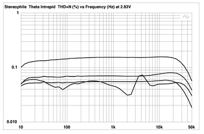
Fig.5 Theta Intrepid, THD+N (%) vs frequency at 2.83V into (from bottom to top at 1kHz): simulated loudspeaker load, 8 ohms, 4 ohms, 2 ohms.

Fig.6 Theta Intrepid, 1kHz waveform at 2.5W into 8 ohms (top), distortion and noise waveform with fundamental notched out (bottom, not to scale).

Fig.7 Theta Intrepid, spectrum of 50Hz sinewave, DC-1kHz, at 25W into 8 ohms (linear frequency scale).
Like Theta's Citadel monoblock, the Intrepid has no loop negative feedback, and correspondingly has increasing levels of harmonic distortion as the power increases. Fig.7, for example, was taken at 25W into 8 ohms, well below the specified output power, but still has 0.6% of third harmonic and 0.1% of second harmonic distortion. As a result, on the admittedly demanding high-frequency, high-power intermodulation test, the Intrepid produces noticeably high levels of higher-order products (fig.8), even though the 1kHz difference product remains at -60dB (0.1%).

Fig.8 Theta Intrepid, HF intermodulation spectrum, DC-24kHz, 19+20kHz at 76W into 4 ohms (linear frequency scale).
As both positive and negative speaker terminals are actively driven, the Theta could not be tested with the Miller Audio Research Amplifier Profiler, which connects the negative terminal to ground. However, using the Audio Precision System One, which has floating inputs, I plotted the Intrepid's continuous output power into 8, 4, and 2 ohm resistive loads (fig.9). The increase in THD with increasing power can be clearly seen in this graph, as can the fact that the amplifier meets its specified 100W output into 8 ohms at 2% THD rather than the usual 1%. Into 4 ohms, the clipping point had to be further relaxed to 3% THD+N for the Intrepid to meet its 200W specification, even though just one channel was driven for this measurement.

Fig.9 Theta Intrepid, distortion (%) vs continuous output power into (from bottom to top at 10W): 8 ohms, 4 ohms, 2 ohms.
The designer's decision not to use global negative feedback has resulted in an amplifier that produces rather more distortion at moderate power levels than I would like to have seen, even though this distortion is predominantly the subjectively fairly innocuous third harmonic.—John Atkinson
|
|
| ||||||||||
- Log in or register to post comments


| Loudspeakers Amplification Digital Sources | Analog Sources Accessories Featured | Music Columns Retired Columns | Show Reports | Features Latest News Community | Resources Subscriptions |
 © 2024 Stereophile
AVTech Media Americas Inc., USA
All rights reserved

