| Columns Retired Columns & Blogs |
Onkyo DX-7555 CD player Measurements
Sidebar 3 Measurements
To measure the Onkyo DX-7555, I used the magazine's older Audio Precision System One and a brand-new Audio Precision System SYS2722 kindly loaned by AP (see "As We See It" and Audio Precision's website), as well as the Miller Audio Research Jitter Analyzer.
The DX-7555 offered excellent error correction, producing no audible glitches in its output until the Pierre Verany Test CD's track 32, the data spiral of which includes 1mm gaps. The Onkyo's maximum output level at 1kHz was 2.06V, close to the CD standard's 2V, and it preserved absolute polarity; ie, was non-inverting. Its output impedance was a moderately low 411 ohms at high and middle frequencies, rising inconsequentially to 426 ohms at 20Hz; both figures are close to the specified 470 ohms.
With the filter set to "Sharp," the Onkyo's frequency response was flat within most of the audioband, with a slight top-octave droop to –0.25dB at 20kHz (fig.1, top pair of traces). With pre-emphasized data (fig.1, bottom traces), the droop began a little lower in frequency. With the filter set to "Slow," the output dropped rapidly above 15kHz (fig.1, middle traces). Channel separation (not shown) was superb at >110dB in the midrange and was still an excellent 83dB at 20kHz.

Fig.1 Onkyo DX-7555, frequency response into 100k ohms with normal data and filter set to "Sharp" (top), set to "Slow" (middle at 20kHz), and with pre-emphasized data set to "Sharp" (bottom). (Right channel dashed, 0.5dB/vertical div.)
For continuity with my existing library of CD player measurements, I looked at the spectrum of the DX-7555's output while it played back a dithered 1kHz tone at –90dBFS, using the AP System One to sweep a 1/3-octave bandpass filter from a center frequency of 20kHz to 20Hz. The result is shown in fig.2. The noise floor is basically that of the dither noise on the test CD, but there is a suspicious-looking hump at twice the fundamental frequency in the right-channel trace. FFT analysis of the player's output (fig.3) reveals that there is some second-harmonic distortion present in the right channel (though not the left).
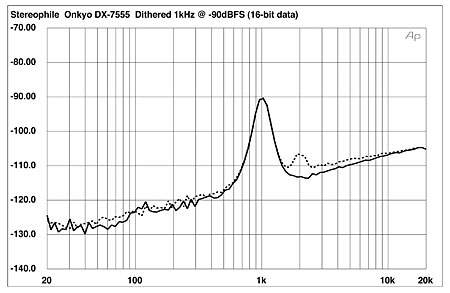
Fig.2 Onkyo DX-7555, 1/3-octave spectrum with noise and spuriae of dithered 1kHz tone at –90dBFS, 16-bit CD data (right channel dashed).
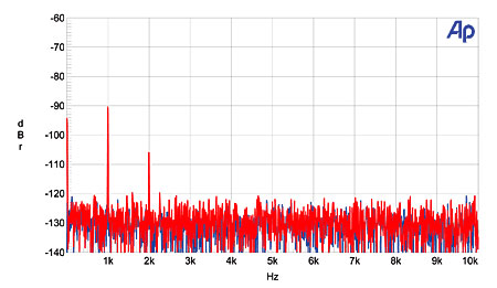
Fig.3 Onkyo DX-7555, FFT-derived spectrum of 1kHz sinewave at –90dBFS, 16-bit data (linear frequency scale; left channel blue, right channel red).
This behavior is sometimes associated with negative linearity error, as a DAC problem pushes energy from the fundamental into the harmonic, but the Onkyo's plot of linearity error was fine (fig.4) and dominated by the recorded dither noise in both channels. The right-channel distortion on low-level tones must therefore have been an analog circuitry problem, which is hinted at by the asymmetry of the right-channel waveform of an undithered 1kHz tone at exactly –90.31dBFS (fig.5, red trace). (Unless a DC offset is present, waveform asymmetry is always associated with the presence of even-order distortion.) By comparison, the left-channel waveform (fig.5, blue trace) is perfectly symmetrical. But note how the Onkyo clearly resolves in both channels the three DC voltage levels described by the digital data.
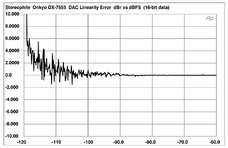
Fig.4 Onkyo DX-7555, left-channel departure from linearity, 16-bit data (2dB/vertical div.).
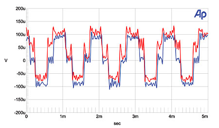
Fig.5 Onkyo DX-7555, waveform of undithered 1kHz sinewave at –90.31dBFS, 16-bit data (left channel blue, right channel red).
At high levels into high impedances in the midrange, the distortion was both low in level and primarily the benign second, third, and fourth harmonics (fig.6). At low frequencies into both high and low impedances, however, the second harmonic was the highest in level, but, at –94dB (0.002%), this is negligible (fig.7). Intermodulation distortion with the reconstruction filter set to "Sharp" was vanishingly low, even into very low impedances (fig.8).

Fig.6 Onkyo DX-7555, spectrum of 50Hz sinewave at 0dBFS into 600 ohms (linear frequency scale; left channel blue, right channel red).
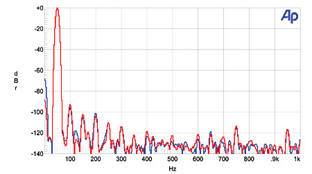
Fig.7 Onkyo DX-7555, spectrum of 1kHz sinewave at 0dBFS into 600 ohms (linear frequency scale; left channel blue, right channel red).
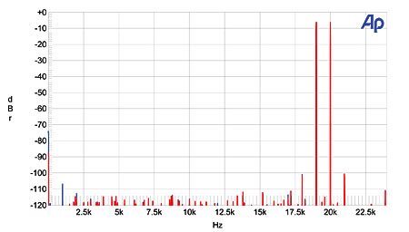
Fig.8 Onkyo DX-7555, unbalanced HF intermodulation spectrum, 19+20kHz at 0dBFS peak into 600 ohms (linear frequency scale; left channel blue, right channel red).
Finally, I assessed the Onkyo's rejection of word-clock jitter with both the Miller and Audio Precision analyzers. The Miller reported just 279 picoseconds peak–peak of word-clock jitter, this primarily in the data-related sideband pair at ±230Hz and the power-supply–related sideband pair at ±120Hz. These two pairs of sidebands can be seen in the AP-generated graph (fig.9); the more widely spaced sidebands are the high-order harmonics of the low-frequency squarewave and are at the residual level.
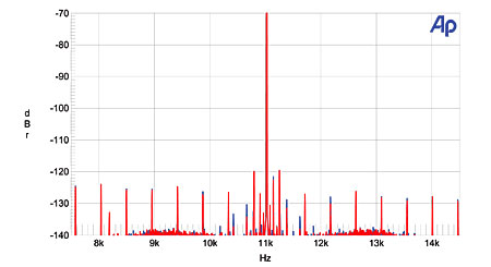
Fig.9 Onkyo DX-7555, high-resolution jitter spectrum of analog output signal (11.025kHz at –6dBFS, sampled at 44.1kHz with LSB toggled at 229Hz), 16-bit CD data. Center frequency of trace, 11.025kHz; frequency range, ±3.5kHz (left channel blue, right channel red).
Overall, this is excellent measured performance.—John Atkinson
NEXT: Wes Phillips on the Onkyo »
|
|
| ||||||||||
- Log in or register to post comments


| Loudspeakers Amplification Digital Sources | Analog Sources Accessories Featured | Music Columns Retired Columns | Show Reports | Features Latest News Community | Resources Subscriptions |
 © 2024 Stereophile
AVTech Media Americas Inc., USA
All rights reserved

