| Columns Retired Columns & Blogs |
Myryad MDP 500 preamplifier-processor Measurements
Sidebar 3:Measurements
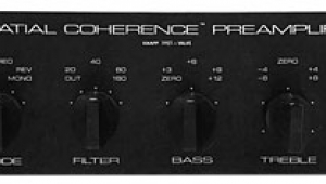
I measured the Myryad MDP 500's performance through all three sets of inputs: digital, analog, and multichannel analog. (The last are the only ones fed to the outputs without being digitized.) The input impedance via both sets of analog inputs was a moderate 16.7k ohms at 1kHz. The MDP 500's output impedance was a low (good) 59 ohms at 1kHz, rising slightly and inconsequentially to 68 ohms at 20Hz and 61 ohms at 20kHz.
With the volume control set to "0" and the A/D analog sensitivity set to "–3," which is how Kal Rubinson had used the unit, a 1V input level resulted in an output level of 711mV, a drop of almost exactly 3dB. Via the multichannel analog inputs, with the volume control set to "0," there was an inconsequential insertion loss of 0.25dB. Feeding the digital input with data representing a full-scale 1kHz tone gave an analog output level of 2.063V, again with the volume control set to "0."
The frequency response via the digital input is shown in fig.1 (top traces): flat through the entire band, with excellent low-frequency extension. With a pre-emphasized signal (lower traces), there is a hint of a swayback in the mid-treble, but this is again inconsequential. The top pair of traces in fig.2 show the Myryad's frequency response taken through its multichannel analog inputs. As is appropriate for use with multichannel SACD and DVD-Audio players, this extends well above the audioband, dropping to –3dB at almost 200kHz. Via the regular analog inputs (lower traces), however, the response is curtailed at both ends of the spectrum. In particular, the output drops like a stone above 20kHz, due to the comparatively restricted bandwidth of the A/D circuitry, which operates at 48kHz.

Fig.1 Myryad MDP 500, digital input, frequency response at –12dBFS, without emphasis (top) and with emphasis (bottom). (Right channel dashed, 0.5dB/vertical div.)

Fig.2 Myryad MDP 500, frequency response at 1V output of multichannel analog input (top) and regular analog input (bottom). (Right channel dashed, 0.5dB/vertical div.)
Channel separation was good via all inputs, at around 100dB in the midband, though, as can be seen in fig.3, it rose somewhat with increasing frequency, more in the L–R direction than in the R–L direction.

Fig.3 Myryad MDP 500, channel separation via multichannel analog inputs (LF–RF dashed, 10dB/vertical div.).
The MDP 500's D/A converters have only moderate resolution, as illustrated in fig.4, which shows a spectral analysis of the preamp's output as it decoded data representing a dithered 1kHz tone at –90dBFS, with word lengths of both 16 and 24 bits. The noise floor is higher than we usually see with the best CD playback sections. In addition, the increase in word length drops that noise floor by only 1.5dB, and then only in the treble. Crystal's "20-bit" specification for the DAC chip used in the MDP 500 is thus very optimistic.

Fig.4 Myryad MDP 500, digital input, 1/3-octave spectrum of dithered 1kHz tone at –90dBFS, with noise and spuriae, 16-bit (top) and 24-bit (bottom) data (right channel dashed).
This disappointing measured performance can also be seen in fig.5, a spectral analysis of the player's analog output signal while it decoded 16- and 24-bit "digital black." A large increase in energy appears above the audioband, due to the D/A converter's delta-sigma topology. Given the Myryad processor's need to use six DACs compared with the two found in a CD player, which will place price constraints on the parts used, and that KR liked the sound of the MDP 500's digital input, I might be making too much of this—but I still would like to have seen higher resolution. Perhaps the replacement DACs scheduled for the product will offer this.

Fig.5 Myryad MDP 500, digital input, 1/3-octave spectrum of "digital black" with noise and spuriae, 16-bit (top) and 24-bit (bottom) data (right channel dashed).
The DACs offer good linearity, however, any level error remaining below 2dB to below –103dBFS (fig.6). Correlating with figs.4 and 5, the noise floor in this graph is higher than usual, and this results in a noisy reproduction of an undithered 16-bit waveform at –90.31dBFS (fig.7). (With the better DACs, this waveform's three voltage levels can be clearly seen.) The ADC's linearity error (not shown) was of the same order as the DAC's.
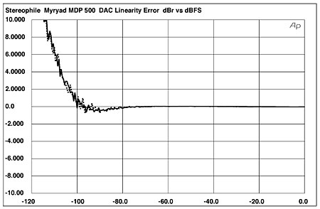
Fig.6 Myryad MDP 500, digital input, departure from linearity, 16-bit data (2dB/vertical div., right channel dashed).

Fig.7 Myryad MDP 500, digital input, waveform of undithered 1kHz sinewave at –90.31dBFS, 16-bit data.
When an analog signal is digitized, it is important that the ADC not be driven into overload, which is why the MDP 500's setup screens pay attention to the sensitivity of the analog inputs. As I mentioned earlier, KR had set these inputs to –3dB; fig.8 shows the percentage of THD+noise in the Myryad's analog output plotted against the analog input voltage. The level of distortion drops steadily with increasing input level until 3.25V is reached, above which the THD rises dramatically, indicating that the ADC is in overload. However, I can't think of any consumer source components with which the MDP 500 would be used that would reach 3.25V. Even with the sensitivity increased to "0," the overload point would be 2.3V—just above the nominal maximum CD output—meaning that the component's analog input headroom has been sensibly arranged.
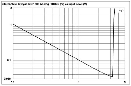
Fig.8 Myryad MDP 500, analog input, THD+N (%) vs input level (V), sensitivity set to "–3."
There is no such restriction on input level via the multichannel analog inputs; fig.9 is a similar graph plotting THD+N against input level for these inputs. With the volume control at "0," the clipping point (defined as 1% THD+N) is not reached until an input level of 9V, and the distortion is 10 times lower than via the regular analog inputs.

Fig.9 Myryad MDP 500, multichannel analog input, THD+N (%) vs input level (V).
Via the digital input, the distortion spectrum (fig.10) was very clean, with only a shadow of second harmonic raising its head above the –100dB level (0.001%). This graph was taken into a high 100k ohm load; dropping the load to the torturous 600 ohms (fig.11) raised the second harmonic to –80dB (0.01%), with now the third harmonic making an appearance at –90dB (0.003%). Via the regular analog inputs into 100k ohms (fig.12), even at a slightly lower level, the second harmonic lay at –80dB, which is presumably due to the A/D converter.

Fig.10 Myryad MDP 500, digital input, spectrum of 50Hz sinewave, DC–1kHz, at 0dBFS into 100k ohms (linear frequency scale).

Fig.11 Myryad MDP 500, digital input, spectrum of 50Hz sinewave, DC–1kHz, at 0dBFS into 600 ohms (linear frequency scale).

Fig.12 Myryad MDP 500, analog input, spectrum of 50Hz sinewave, DC–1kHz, at 1V into 100k ohms (linear frequency scale).
While intermodulation distortion via this same analog input was very low in level (fig.13), the picture was not so good for digital input signals. Fig.14 reveals that actual intermodulation products are vanishingly low in level (at least into the 100k ohm load, the 600 ohm load introducing both first- and second-order components), but the analog noise floor rises around the fundamental 19kHz and 20kHz tones. Assuming that this isn't a function of some poorly implemented DSP, which seems unlikely, such behavior usually indicates the presence of word-clock jitter.

Fig.13 Myryad MDP 500, analog input, HF intermodulation spectrum, DC–24kHz, 19+20kHz at 2V into 100k ohms (linear frequency scale).

Fig.14 Myryad MDP 500, digital input, HF intermodulation spectrum, DC–24kHz, 19+20kHz at 0dBFS into 100k ohms (linear frequency scale).
To test for the presence of jitter, I drive the device under test with an unusual analytical signal developed by the late Julian Dunn in the UK (fig.15). A high-level sinewave is encoded at exactly one quarter the sample rate, which results in consecutive pairs of identical samples either side of the time line (indicated with red blobs). The blue line represents the analog waveform produced by these samples after the analog signal output by the DAC has been processed by the low-pass reconstruction filter; you can see that it is indeed a sinewave, despite the apparent paucity of waveform information encoded by the samples. Not visible in this graph at the scale at which it must be reproduced in the magazine is the second signal component: a 229Hz squarewave with an amplitude of 1LSB. This is encoded by all 16 bits switching on and off at the 229Hz rate, which is very much the worst case for the introduction of word-clock jitter.
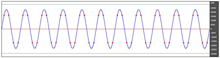
Fig.15 Waveform of Dunn analytical signal, fundamental frequency 11.025kHz, sample rate 44.1kHz.
To detect jitter, the Miller Audio Research Jitter Analyzer averages 64 high-resolution spectra of the device under test's analog output signal while it decodes the Dunn signal, and searches the resultant FFT bins for sideband pairs around the 11.025kHz fundamental. The grayed-out trace in fig.16 shows a typically good result on this test, in this case the Musical Fidelity X-24K D/A processor, which has both a low noise floor and low levels of jitter sidebands (251.5 picoseconds peak–peak). By contrast, the MDP 500's jitter spectrum (solid trace) has a significantly higher level of random noise with an unusual double-humped profile; and high levels of data-related sidebands (red numeric markers) and of sidebands related harmonically to the AC power-supply frequency of 60Hz (brown and blue numeric markers). The main data-related components lie at ±229Hz (red "2") and contribute no less than 1832ps of jitter.

Fig.16 Myryad MDP 500, high-resolution jitter spectrum of analog output signal, driven via 6' S/PDIF datalink from PS Lambda transport (11.025kHz at –6dBFS with LSB toggled at 229Hz). Center frequency of trace, 11.025kHz; frequency range, ±3.5kHz. (Grayed-out trace is Musical Fidelity X-24K under identical circumstances.)
This may look worse than it sounds. Remember that Kal Rubinson did prefer the sound of the MDP 500's digital inputs to its digitized analog inputs, which "elevated it into an entirely glorious realm of transparency and openness." But, again, I would have preferred not to see such measured behavior.—John Atkinson
|
| ||||||||||
- Log in or register to post comments


| Loudspeakers Amplification Digital Sources | Analog Sources Accessories Featured | Music Columns Retired Columns | Show Reports | Features Latest News Community | Resources Subscriptions |
 © 2024 Stereophile
AVTech Media Americas Inc., USA
All rights reserved

