| Columns Retired Columns & Blogs |
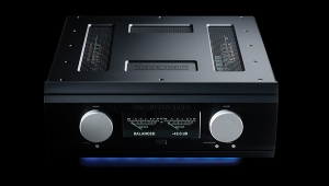
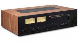
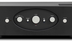
Musical Fidelity X-T100 integrated amplifier Measurements
Sidebar 3: Measurements
Footnote 1: I was confused by what appeared to be competing specifications for the XT-100's maximum output power. The Musical Fidelity website says 50W into 8 ohms, 80W into 4 ohms, whereas the owner's manual has it as 70Wpc into 8 ohms, 100W into 4 ohms, though they agree on the maximum voltage swing—67V p–p. The latter is equivalent to a maximum power of 70Wpc into 8 ohms, so that is what I took to be the specified power. Perhaps it depends on whether the owner uses the bundled Triple-X power supply or opts for the more-expensive Triple-X170 supply.—John Atkinson
Before performing tests on an amplifier, I thermally stress it by running both channels for 60 minutes into 8 ohms at one-third the specified power—23Wpc, in the case of the Musical Fidelity X-T100 with its Triple-X power supply. With its limited heatsink area, I wasn't surprised that the X-T100 quickly got hot under these conditions. Its side-mounted heatsinks were too hot to touch after 15 minutes, with a hot spot at the rear of the baseplate. The distortion level didn't change during this period, beginning and ending at a low 0.0055%, but I ended the preconditioning after 30 minutes with the amplifier chassis too hot to touch and smelling of heated metal.
The maximum gain for line-level inputs was 42.9dB from the speaker outputs, 12.7dB from the preamplifier output jacks, both figures typical of the genre. The phono input was compatible with moving-magnet cartridges, with a maximum gain measured at the preamp outputs of 53.2dB. Both phono and line inputs preserved absolute polarity at both the preamp and speaker outputs. The line input impedance was 48k ohms at low and middle frequencies, dropping inconsequentially to 38k ohms at 20kHz. These figures are lower than the specified 220k ohms, but this won't be a problem. The phono-stage input impedance, specified as 47k ohms, ranged from 48k ohms at 20Hz to 58k ohms at 20kHz.
Looking first at the phono stage, assessed at the preamplifier output jacks, the overload margin was a good 16.6dB across the audioband (ref. 5mV at 1kHz), though this is lower than the specified 24dB. The RIAA equalization was accurate (fig.1), with the channels quite well matched. The maximum error was +0.25dB at 20Hz in the right channel, though both channels rolled off slightly at the top of the audioband, reaching –0.5dB left channel and –0.35dB right, at 20kHz. The line input's frequency response, again measured at the preamp output (not shown), had an identical rolloff at 20kHz to the phono stage.

Fig.1 Musical Fidelity X-T100, phono-stage RIAA error at 1mV input at 1kHz (0.5dB/vertical div., right channel dashed).
The X-T100 preamplifier's output impedance is specified at 47 ohms, but I measured rather higher, at 92 ohms at high and middle frequencies, rising to 467 ohms at 20Hz. These figures are still low in absolute terms, however. The X-T100's output impedance at the speaker terminals was a little on the high side for a solid-state design, at 0.16 ohm at 20Hz and 1kHz, rising slightly to 0.22 ohm at 20kHz. The modification of the amplifier's response, due to the Ohm's Law interaction between this output impedance and the impedance of the loudspeaker, is still mild, however. The variation remained within ±0.2dB limits (fig.2, top dashed trace) with our standard simulated loudspeaker. The slight increase in output impedance at 20kHz slightly accentuates the preamp stage's top-octave rolloff into the lower load impedances, though at –0.75dB at 20kHz this is still mild, and doesn't compromise the shape of a 10kHz squarewave (fig.3). This is also commendably free from overshoot and ringing.

Fig.2 Musical Fidelity X-T100, frequency response at 2.83V into (from top to bottom at 2kHz): simulated loudspeaker load, 8, 4, 2 ohms (0.5dB/vertical div., right channel dashed).

Fig.3 Musical Fidelity X-T100, small-signal 10kHz squarewave into 4 ohms.
Channel separation, measured at the speaker terminals, was disappointing, particularly in the L–R direction, which measured 54dB across most of the band (fig.4). It was almost 20dB higher in the other direction, and looking at the measured separation at the preamplifier output jacks (not shown), the crosstalk seems to occur mostly ahead of the power-amplifier section. The phono stage's channel separation was also disappointing, at 40–45dB in both directions across much of the audioband, though it's fair to point out that this is still at least 10dB better than the separation of a typical phono cartridge. The X-T100's signal/noise ratio, again assessed at the speaker terminals with the volume control at its maximum, was good, at 66.8dB (wideband, unweighted, ref.1 W into 8 ohms). This result improved to 77.3dB when A-weighted.

Fig.4 Musical Fidelity X-T100, channel separation (R–L dashed, 10dB vertical div.).
Plotting the X-T100's continuous-output power delivery against the THD+noise percentage with a 1kHz signal revealed that the amplifier just failed to meet its specified maximum power (footnote 1) at our usual definition of clipping of 1% THD+N (fig.5). The output powers into 8 and 4 ohms at 1% THD+N were 66W (18.2dBW) and 90W (16.5dBW), respectively. (The wall AC voltage was 123V during these tests.) However, the Musical Fidelity did meet its specified power of 70W into 8 ohms (18.45dBW) and 100Wpc into 4 ohms (17dBW) at 3% THD+N. It also met its specified power using a low–duty-cycle toneburst at 1kHz (fig.6). The amplifier can be seen to be working hard into 2 ohms, however, with a large increase in THD even at fairly low powers.
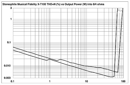
Fig.5 Musical Fidelity X-T100, distortion (%)vs 1kHz continuous output power into (from bottom to top at 100W): 8, 4 ohms.

Fig.6 Musical Fidelity X-T100, THD+N (%)vs frequency at 10V into (from bottom to top): 8, 4, 2 ohms (right channel dashed).
Distortion was generally very low, especially into higher impedances, which can be seen in fig.7, which plots the THD+N percentage against frequency at a moderate output level of 10V. Only into 2 ohms does the THD rise at higher frequencies, but even then remains well below 0.1%. At midrange frequencies, the distortion is predominantly the subjectively benign third harmonic (fig.8), though at high powers and low frequencies this is joined by the second harmonic (fig.9). Note the very low level of the 120Hz power-supply component in this graph and the absence of spuriae at 70Hz and 170Hz, suggesting that the X-T100's power supply is well designed, even with the transformer's remote location. Even close to clipping into 4 ohms, the MF's levels of intermodulation distortion were low (fig.10), and again, no power-supply–related spuriae can be seen.
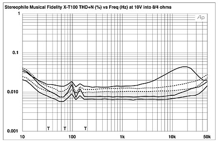
Fig.7 Musical Fidelity X-T100, 1kHz waveform at 39W into 4 ohms (top), 0.007% THD+N; distortion and noise waveform with fundamental notched out (bottom, not to scale).

Fig.8 Musical Fidelity X-T100, spectrum of 50Hz sinewave, DC–1kHz, at 50W into 8 ohms (linear frequency scale).

Fig.9 Musical Fidelity X-T100, HF intermodulation spectrum, DC–24kHz, 19+20kHz at 90.25W peak into 4 ohms (linear frequency scale).

Fig.10 Musical Fidelity X-T100, HF intermodulation spectrum, DC–24kHz, 19+20kHz at 90.25W peak into 4 ohms (linear frequency scale).
Other than the reduced channel separation, this is generally excellent measured performance, though X-T100 owners should avoid using speakers that dip much below 4 ohms, I feel. One thing that did bother me: The RCA jacks used by Musical Fidelity were not totally compatible with the Neutrik RCA plugs with which all my test-lab cables are fitted. After the usual plugging and unplugging, some of the contacts became intermittent. Take your Musical Fidelity dealer's advice on what cables/connectors work best with the X-T100.—John Atkinson
Footnote 1: I was confused by what appeared to be competing specifications for the XT-100's maximum output power. The Musical Fidelity website says 50W into 8 ohms, 80W into 4 ohms, whereas the owner's manual has it as 70Wpc into 8 ohms, 100W into 4 ohms, though they agree on the maximum voltage swing—67V p–p. The latter is equivalent to a maximum power of 70Wpc into 8 ohms, so that is what I took to be the specified power. Perhaps it depends on whether the owner uses the bundled Triple-X power supply or opts for the more-expensive Triple-X170 supply.—John Atkinson
NEXT: Sam Tellig, February 2007 »
|
| ||||||||||
- Log in or register to post comments


| Loudspeakers Amplification Digital Sources | Analog Sources Accessories Featured | Music Columns Retired Columns | Show Reports | Features Latest News Community | Resources Subscriptions |
 © 2024 Stereophile
AVTech Media Americas Inc., USA
All rights reserved

