| Columns Retired Columns & Blogs |
MBL 111 loudspeaker Measurements
Sidebar 3: Measurements
The MBL's impedance measurement (fig.1) was made with an Audio Precision System One. Although it reaches a minimum value of 4 ohms at 12kHz, the magnitude stays above 6 ohms for most of the upper midrange and treble. It does drop to 5 ohms or below in the upper- and midbass, which means using a good amplifier capable of sourcing current. Note the combination of lowish impedance (around 5 ohms) and large, capacitive phase angle (45° or so) in a narrow region around 36Hz. This will tax the partnering amplifier and might explain why the speaker's low-frequency character seemed so dependent on the choice of amplifier.

Fig.1 MBL 111, electrical impedance (solid) and phase (dashed) (2 ohms/vertical div.).
Because Santa Fe's 7000' altitude reduces the sensitivity of all loudspeakers, I calculate sensitivity by comparing the measured, B-weighted level at 50" for a given voltage input, using a noise signal, with that obtained for a sample Rogers LS3/5A that I've measured both in Santa Fe and at sea level. The MBL's B-weighted sensitivity was very low, my estimated 80.2dB/2.83V/m agreeing with the specification. To some extent, however, this will be offset by the speaker's behavior in a room. Unlike a conventional forward radiator, the MBL 111's unique design means that it puts out sound equally in all lateral directions. The power output into a room will therefore be greater than suggested by the low on-axis sensitivity. Nevertheless, as I found in my auditioning, the MBL will need to be driven by a goodly powerful amplifier to achieve realistic sound pressure levels.
All the acoustic measurements of the MBL 111 were taken with the DRA Labs MLSSA system and a calibrated B&K 4006 microphone. I place the speaker under test on a turntable/stand so as to place its tweeter about halfway between the listening-room floor and ceiling and midway between the sidewalls. Then, on the floor between the speaker and microphone, I construct an acoustic "black hole" out of graded layers of acoustic foam and fiberglass damping material, which kills the forward floor reflections of the sound emitted by the speaker. To minimize reflections from the test setup, the measuring microphone is flush-mounted inside the end of a long tube. The primary reflection in the MLSSA's calculated impulse response is, therefore, that of the tweeter from the ceiling, which arrives about 4ms after the direct sound. This 4ms reflection-free time window results in a measurement valid down to 300Hz or so.
The frequency response is calculated from the windowed impulse response using the Fast (Discrete) Fourier Transform, and is corrected for the measuring microphone's on-axis departure from a flat response. I then take the impulse responses of the low-frequency drivers and ports in the nearfield, with the tip of the microphone capsule almost touching the centers of their cones/apertures, and append these responses to the upper-frequency ones. To calculate the overall low-frequency rollout, DRA Labs' software allows you to add the complex responses (amplitude and phase) of the contributing drivers in the ratio of the square roots of their radiating areas; it also compensates for the different distances from each source to a nominal farfield mike position.
The individual nearfield responses, plotted below 1kHz, of the MBL's bandpass woofer and upper- and lower-midrange units are shown in fig.2. The woofer's nearfield –6dB point is a low 26Hz. As is typical of a bandpass unit, the ultimate LF rollout is the 12dB/octave typical of a sealed enclosure rather than a reflex design's 24dB/octave. As I found, this gives good in-room bass extension. The woofer crosses over at the specified 130Hz to the lower-midrange driver, which in turn crosses over to the omnidirectional upper-midrange unit at 670Hz, again as specified. The usual high-frequency resonance featured by bandpass designs is apparent at 580Hz, but is well-suppressed by the crossover.
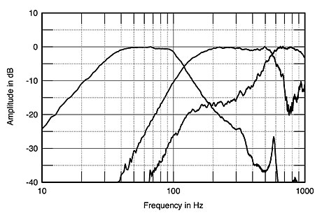
Fig.2 MBL 111, low-frequency nearfield acoustic crossover.
The overall response of the MBL 111 on the reference axis (level with the top of the tweeter magnet) and averaged across a 30° horizontal angle is shown in fig.3. While the overall balance is respectably flat, it is broken up by a number of small peaks and dips in the treble. These are probably due to reflections of the drive-units' outputs from the various magnet structures and structural rods in the vicinity. Certainly I was not bothered by any colorations in the treble that might be ascribed to this measured response. The speaker's output drops rapidly above 20kHz.

Fig.3 MBL 111, anechoic response on optimal axis at 50", averaged across 30° horizontal window and corrected for microphone response, with complex sum of nearfield woofer-port and lower-midrange responses plotted below 300Hz.
It can be seen from fig.4, the MBL's lateral dispersion plot, that the speaker is a true omnidirectional design, at least in the lateral plane. It can also be seen that the dips in the on-axis response tend to fill in to the speaker's sides. The cursor position shows a slight lack of off-axis energy in a frequency region (around 3kHz) where the axial output has a small peak. (Only the differences between the off-axis responses and the on-axis response are shown in this graph, which means that the latter looks like a straight line.) In the vertical plane (fig.5), despite the very close spacing of the three upper-range drivers, there appears to be some criticality as to exact listening axis. If you sit too low, a lack of energy makes its presence known in the upper crossover region.
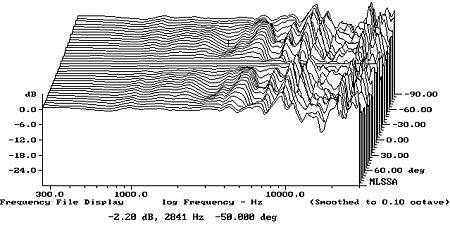
Fig.4 MBL 111, horizontal response family at 50", normalized to response on optimal axis, from back to front: differences in response 90°–5° off-axis; reference response; differences in response 5°–90° off-axis.
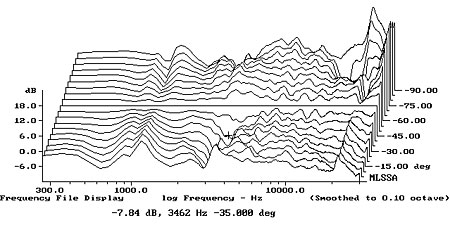
Fig.5 MBL 111, vertical response family at 50", normalized to response on tweeter axis, from back to front: differences in response 45°–5° above tweeter axis; reference response; differences in response 5°–45° below tweeter axis.
Fig.6 shows an in-room spectral analysis for the MBLs, with the speakers placed at the original positions. To obtain this curve, I use an Audio Control Industrial SA-3050A spectrum analyzer with its own microphone. I average six measurements at each of 10 separate microphone positions for left and right speakers individually, giving a total of 120 original spectra. These are then averaged to give a curve that, in my room, has proved to give a good correlation with a loudspeaker's perceived balance. (The averaging minimizes the effects of the low-frequency room resonances on the curve.) Note that the entire woofer region in fig.6 is boosted by about 4–5dB compared with the 1kHz reference level. This would explain the rather heavy bass, as well as the sensitivity of the speaker's LF balance to small changes in positioning and setup. The in-room bass extension is excellent, however.

Fig.6 MBL 111, spatially averaged, 1/3-octave response in JA's room.
At the other end of the frequency scale, the treble is smooth and flat, though with a rather rolled-off top octave. This correlates with the uncolored but rather "sweet" HF balance I noted in my auditioning. It was also very dependent on the room furnishings and the distance of the speakers from the closest walls. Things are more problematical in the midrange in this graph. In their initial positions, chance would have it that the lower-midrange drivers were equidistant from the floor and the rear wall. Because the MBL's omnidirectional nature means that reflections from boundaries will be much stronger than is the case with forward radiators, interference effects will also be more strong. Here, the coincidence of boundary distance has given rise to a severe lack of lower-midrange energy, which I heard as a rather lean quality to male vocals. Moving the speakers farther away from the rear wall ameliorated this problem, but further depressed the speaker's top octave. As I found in my auditioning, the MBL 111 requires very careful setup to optimize the balance between its bass, midrange, and treble.
In the time domain, the MBL's step response (fig.7) indicates that all the drive-units are connected with the same positive acoustic polarity. Note, however, the severe glitches between 7ms and 8ms: these are reflections from the room boundaries that are much stronger than is usually the case, due to the speaker's omnidirectional nature. Note also the little glitches between 4ms and 5ms: these are reflections of the upper-frequency driver outputs from the supporting structure that I referred to earlier. The 111's waterfall plot (fig.8) appears to have a lot of resonant behavior in the high treble. However, this plot is very susceptible to the presence of reflections; I suspect that that is what we are seeing here.
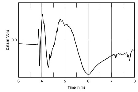
Fig.7 MBL 111, step response on optimal axis at 50" (5ms time window, 30kHz bandwidth).
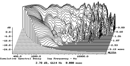
Fig.8 MBL 111, cumulative spectral-decay plot on optimal axis at 50" (0.15ms risetime).
Finally, both of the MBL's enclosures seemed very dead to the knuckle-rap test. To more formally investigate the cabinets' resonant behavior, I placed the speaker on upturned cones (which allows all the various modes to develop to their fullest) and excited it with a 2kHz–bandwidth MLS signal at a level of 7.55V RMS. (See Stereophile, June 1992, p.205; and September 1992, p.162.) I then use a simple PVDF plastic-tape accelerometer (similar to a piezoelectric acoustic guitar pickup) to capture the impulse response of each panel. The MBL's panels were indeed very inert. The only resonant mode I could detect is shown in fig.9, taken with the accelerometer taped to the upward-facing baffle of the lower-midrange enclosure. Low in frequency at 125Hz, this resonance is, I suspect, actually due to the interaction between the speaker's mass and the sprung wooden floor in the Stereophile listening room. While I could hear it in that room when I struck the enclosure with my fist, it appeared to be absent in my own listening room.

Fig.9 MBL 111, cumulative spectral-decay plot of accelerometer output fastened to baffle next to upward-firing midrange unit. (MLS driving voltage to speaker, 7.55V; measurement bandwidth, 2kHz.)
Summing up, this is an interesting set of measurements, confirming the MBL's significant interaction with the room and the corresponding need for careful setup.—John Atkinson
|
| ||||||||||
- Log in or register to post comments


| Loudspeakers Amplification Digital Sources | Analog Sources Accessories Featured | Music Columns Retired Columns | Show Reports | Features Latest News Community | Resources Subscriptions |
 © 2024 Stereophile
AVTech Media Americas Inc., USA
All rights reserved

