| Columns Retired Columns & Blogs |
Mark Levinson No.31 Reference CD transport Page 2
Many products have been described as having excellent build quality and fit'n'finish. The No.31 transcends such descriptions and previous assessments of product build. The lavish standard to which the No.31 is built is beyond previous measure. Even the smallest details—such as the way the LEDs fit into the front panel, or the color and grain matching between chassis parts—are executed with extraordinary precision and craftsmanship. The No.31 is a work of art.
Footnote 4: The objective lens on a CD mastering machine must maintain its distance from the spinning glass master to within ~±0.2 microns to keep the recording beam focused. There are 25.4;um in a thousandth of an inch.
Technical description
The No.31's stunning build quality and unique functions only hint at the sophisticated technology inside the unit. Never before has such a monumental engineering effort been put into recovering data from Compact Disc.
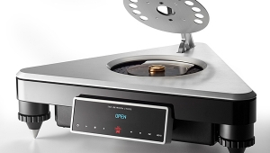
The primary technical goal behind the No.31's design was isolating the disc from vibration. Virtually all aspects of the design and build contribute toward keeping the disc and mechanism stable during playback. This was accomplished in several ways, including the top-loading design, damper, and motorized lid. The most dramatic vibration-isolation feature is, however, the transport mechanism's suspension.
Based on a heavily modified Philips CDM 4 industrial mechanism, the transport subassembly is floated inside the No.31's chassis on large springs filled with foam. A cutout in the panel above the pickup (beneath the lid) provides access for disc changing. Gently pushing on the transport through this cutout gives an idea of the way the mechanism is suspended.
The laser pickup itself would be virtually unrecognizable to its designers; it is encased in a lead sandwich, bringing its weight to an astonishing 14 lbs. The pickup is then suspended on the lead sandwich—chemically sealed to prevent lead poisoning—by a rubber mounting. A recessed bubble level and four hex bolts allow the user to level the transport mechanism.
This entire structure—foam-filled springs, lead sandwich, and suspended pickup—rests on the chassis floor, which is designed to be nonresonant. The chassis is made from three layers of material, two of which are different thicknesses of aluminum with a sheet of damping material between them. Even the No.31's feet are designed to decrease vibration; the user is given the option of compliant feet or spikes. The pickup mechanism itself is thus suspended on the 14-lb lead sandwich, which is mounted to the chassis by the large foam-filled springs. The springs rest on the nonresonant chassis bottom, which sits on damping feet. To give you an idea of the level of mechanical isolation between the outer chassis and spindle, a 70g acceleration applied to a table on which the No.31 is resting reportedly produces just 0.4g at the spindle.
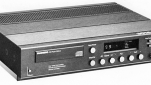
Although these design features isolate the transport from structure-borne vibration, acoustic energy impinging on a disc can also make it vibrate. While it may seem inconsequential, acoustic energy can be a significant source of resonance. I found this dramatically illustrated when I reviewed the Nakamichi 1000mb transport a year ago (in Vol.15 No.6). The 1000mb has an "Acoustic Isolation" door shielding the transport mechanism from acoustic energy. One listen to the difference in musical presentation with the door open and closed illustrated the effect of sound striking the spinning CD. This is where the No.31's large, thick lid comes in. It meets a rubber ring surrounding the plate covering the transport mechanism, forming an acoustically isolated disc-playback chamber.
This lid and seal structure not only prevents sound from reaching the disc, but provides a pitch-black environment for the disc and optical system. In a scheme in which pits on the disc are converted to varying light intensity, it makes sense to keep stray light out of the photodetector. As I'll describe in the listening impressions, the lid's effect on the musical presentation was profound.
There is one more critical component of the No.31's vibration-resistant design: the carbon-fiber damper disc. This lightweight disc, just a little smaller than a CD, is placed over the CD and held to the spindle with a tiny yet powerful neodymium magnet. A layer of damping material covers the damper's bottom side. The damper's purpose is to reduce the CD's vertical displacement (up-and-down motion) during playback. The reduction in vertical motion provided by the damper is reportedly visible to the naked eye. When you consider that the playback lens must be kept at a precise distance from the spinning disc to maintain focus, you can see how reducing up-and-down motion will aid in reading data from the disc (footnote 4). The damper also greatly reduces current drawn by the focus servo system, creating many ancillary benefits (footnote 5).
Madrigal's choice of a lightweight damper disc runs counter to general industry thinking (except Naim, who use a similar magnetic clamping system in their Naim CDS CD player). Many believe that adding mass to the CD makes for smoother rotation and less vibration. Indeed, this is the idea behind many aftermarket CD rings and damper discs. This mass, however, can actually degrade rotational servo performance by slowing servo response and making the motor work harder. Moreover, transports and their rotational servos are designed around a specific mass—that of a CD. Greatly increasing this mass may radically change the transport's operation.
In addition, a CD doesn't spin at a constant speed. Instead, it slows down as the pickup moves toward the outer radius to maintain a constant linear velocity as seen by the laser. When you jump from track 10 to track 1, the motor must increase its speed from about 200 RPM to 500 RPM. According to Madrigal, adding mass to a rotational drive system that was designed to spin only the mass of a CD can degrade its performance and possibly shorten motor life. The No.31's damping disc was designed so that the transport operates within its mass specification. Finally, a lightweight clamping mechanism doesn't increase mechanical coupling between the disc and chassis.
This extraordinary attention to mechanical isolation is just the beginning. The No.31's electronics, servos, power supplies, and digital output stage are no less impressive.
The No.31's two power supplies are located on removable cards in the two towers flanking the unit. One supply feeds the microprocessor and digital circuitry, while the other is dedicated to the servos. The microprocessor supply consists of a large low-noise toroidal transformer, dual bridge rectifiers, large filter caps, and two pre-regulation stages. Additional capacitors form an RF filtering network. The incoming AC is filtered and protected from surges by an MOV.
AC from this supply is sent across the No.31's front to the second supply in the opposite tower. To protect the rest of the circuitry from AC contamination, the AC-carrying wires are shielded in an enclosed steel channel. The servo supply is very similar to the microprocessor supply, but has two pre-regulation stages. Additional regulation is performed on the main boards next to the circuits they supply. The servo board, for example, has eight regulation stages, with each regulator input having its own RFI filter. Electrolytic caps associated with the regulators are bypassed with film types. To preserve DC purity, the No.31's two main pcbs are four-layer, with the interior layers dedicated to ground and carrying DC. This expensive technique not only minimizes noise on the power-supply rails and ground, but also allows more direct routing of the critical digital signals. Madrigal's tradition of superb power-supply design and execution is expanded upon in the No.31.
The No.31's unique functions and user interface are made possible by a Motorola 68HC11 microprocessor running Madrigal's custom software. In combination with Philips chips, the microprocessor-based No.31 can perform functions not possible with standard Philips implementation. Software is contained on a single ROM, mounted in a ZIF (Zero Insertion Force) socket for easy replacement. Note that the microprocessor and servo boards are separate, and located on opposite sides of the transport mechanism.
Handling of the digital signal is performed with utmost care and attention. The HF (High Frequency) signal recovered from the disc is filtered and cleaned up before it reaches the decoder (a Phillips SAA7310). The digital output stage uses a very expensive, mil-spec, temperature-compensated crystal oscillator. This component is critical; it is the timing reference for the output signal. A pulse transformer couples the S/PDIF digital signal to the final output jacks. Although this is a common technique, Madrigal uses an unusual trick to optimize the transformer's performance. A DC voltage biases the transformer on all the time so that the digital signal doesn't cross the ground transition. Madrigal didn't say why, but the company says it found that this technique greatly improved the transformer's performance.
The ST-Type optical output is the higher-bandwidth Hewlett-Packard device (150MHz vs 50MHz for the standard AT&T variety). The AES/EBU output has a 110 ohm output impedance (in accordance with the AES/EBU specification), but can be changed to 10 ohms by adjusting a DIP switch on the output board. RCA and EIAJ optical (Toslink) are also provided. Most users, however, will opt for the ST-Type or AES/EBU output. The No.30 and No.31, along with Madrigal's MDC-1 AES/EBU interconnect, form a fully realized AES/EBU interface. (For some reason, however, the No.30's AES/EBU indicator does not illuminate with the No.31, nor could a Panasonic 3700 DAT recorder lock to the '31's AES output.)
The No.31's level of design is astonishing; there were many other design refinements I didn't have the space to include. No detail has been left to chance. From the mechanical and acoustic isolation, through the digital signal handling, to the unique user interface, the No.31 sets a new standard for CD transport design.
Listening
I had previously thought the No.30 had revealed all its secrets to me. But when it was driven by the No.31 transport in my listening room, my jaw dropped. The No.31 showed me just how much more music could be extracted from the Compact Disc.
Footnote 4: The objective lens on a CD mastering machine must maintain its distance from the spinning glass master to within ~±0.2 microns to keep the recording beam focused. There are 25.4;um in a thousandth of an inch.
Footnote 5: Servo current draw affects other systems—particularly power supplies—and degrades the system's overall performance. This was dramatically illustrated to me when I worked in CD mastering. Our custom mastering machine would occasionally lose control of turntable rotational speed for no apparent reason. After weeks of head-scratching, we discovered that this loss of control occurred exactly at the point where there was a defect in the glass master. This defect—typically a bump in the photoresist coating—caused the focus servo to instantly draw a large current. The focus-servo power supply also supplied a small preamplifier that amplified the turntable's tachometer signal, which was phase-locked to a reference frequency. When the focus-servo current demand was high because of the glass master defect, the power-supply rail to the tachometer preamp was dragged down, causing the tach signal to be lost momentarily and the turntable to break phase lock. Although the No.31 has a huge, heavily regulated, and dedicated servo supply, the disc playback mechanism still works much better when servo current draw is kept to a minimum.
NEXT: Page 3 »
|
|
| ||||||||||
- Log in or register to post comments


| Loudspeakers Amplification Digital Sources | Analog Sources Accessories Featured | Music Columns Retired Columns | Show Reports | Features Latest News Community | Resources Subscriptions |
 © 2024 Stereophile
AVTech Media Americas Inc., USA
All rights reserved

