| Columns Retired Columns & Blogs |
Mark Levinson No.30 Reference Digital Processor Page 2
The other rear-panel connections include two "Communications Ports." These will permit communication between other Mark Levinson 30–series products for greater user control. For example, when using the No.31 CD transport with the No.30, pressing Play on the transport will automatically switch the No.30 to accept the transport's digital signal.
Three digital outputs for driving digital recorders are provided, two XLR and one Toslink. Two of the outputs (one XLR, one Toslink) are in parallel, selected by the record output selection feature described earlier. The signal being listened to appears at the third output, regardless of which source is selected to drive the other two digital outputs. A two-conductor DC input jack finishes off the main chassis's rear panel.
Analog outputs are found on the towers on either side of the main chassis. Unbalanced signals appear on a single pair of RCA jacks, and two stereo pairs of balanced outputs are provided on XLR connectors. Each tower has a DC input jack for connection to the power supply. The PLS-330 supply connects to the No.30 via three DC supply cables: left analog, right analog, and digital supplies.
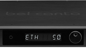
Overall, the No.30's flexibility in accommodating various digital input formats is unprecedented. In addition, the user interface, with direct input-selection buttons, fade-up/down muting, and visual display, provides complete and easy control over what could have been a difficult product to operate.
Technical description
As sophisticated and elaborate as the No.30's industrial and ergonomic designs are, Madrigal pulled out all the stops for the circuitry. The No.30 uses techniques and components never before seen in a digital product. Further, the execution and build quality are extraordinary, even by Madrigal standards. Without question, the No.30 is an engineering tour de force, intended to be a true reference product for many years.
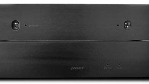
Let's start with the PLS-330 power supply. No other audio component I've seen has had such attention and money lavished on the supply ($4000 of the $13,950 retail price is in the PLS-330).
The PLS-330 contains three main supplies: analog left, analog right, and digital. These correspond to the three DC supply cables connecting the PLS-330 and No.30. The analog supplies are dual-mono construction, running the PLS-330's length on either side of the chassis. The digital supply is a switching type, located between the analog boards. A switching supply was chosen for the digital electronics because of its greater efficiency. The No.30 is packed with current-consuming digital electronics, necessitating the high-current (45W peak) switching supply. To prevent switching noise from getting into other electronics, the switching supply is isolated by an RF shielding can, and digital and analog supply grounds are separate. The switching supply's +8V regulated output is regulated again inside the No.30 to +5V for the input receiver and digital filter, and by a second 5V regulator for all drivers, logic arrays, and support circuitry.
Each linear analog supply (left and right channels) provides regulated +8VDC and ±20.5V at the PLS-330 output, which is regulated a second time inside the No.30. The +8V powers the digital interface in the UltraAnalog DAC, the analog output muting relays, and the digital input receivers. The ±20.5V is re-regulated to ±15V to supply the analog output buffer circuitry and the analog portion of the DACs.
"Regulation" can apply to a wide range of implementations, from a simple shunt zener diode to an ultra-sophisticated multi-component discrete system. The PLS-330's regulation definitely falls into the latter category. Instead of using just a three-pin IC regulator, the PLS-330 features elaborate "discrete hybrid" (ICs with discrete components) circuitry. The analog supply regulation includes three separate sections: a voltage reference stage, voltage gain stage, and an output current gain stage. Each of these sections requires extensive circuitry—reflected in the PLS-330's size and weight. I won't go into further detail, but suffice it to say that this level of regulation is unprecedented in a Mark Levinson product, and perhaps in any audio product. Note that this extraordinary regulation within the PLS-330 is supplemented by additional regulation in the No.30 processor. In the case of the audio circuitry power supply, the elaborate discrete hybrid regulation stage is repeated in each of the No.30's analog stage towers.
Removing the No.30's top cover revealed a design and implementation never before seen in a digital processor. In addition to the extensive logic circuitry needed for the No.30's front-panel display, the treatment of the audio signal—in both digital and analog domains—is extraordinary.
The No.30's main chassis holds three pcbs, stacked one atop the other. The bottom board is the Digital Input Module (DIM), the middle is the No.30's microprocessor-based control section (CPU), and the top board holds the input receiver module, digital filter, and associated components, called the Digital Signal Processing (DSP) board.
Starting with the input stage, each digital input is transformer-isolated and has a dedicated line receiver. Transformer isolation prevents the No.30's grounds from becoming polluted with the source component's noisy grounds. The balanced AES/EBU signal is converted to single-ended for noise rejection, and a custom circuit prevents noise in the digital signal from falsely triggering the receiver. The regulated +8V from the PLS-330 is re-regulated down to +5V by two regulators on the input board.
The microprocessor board is based on a Motorola 68HC11 CPU and two programmable logic arrays. System software is contained in a removable Erasable Programmable Read-Only Memory (EPROM). All the input selection functions, display writing, and digital filter control are performed on the microprocessor board. In addition, some digital filter and S/PDIF decoder module functions are software-controlled. The socketed EPROM allows easy software changes in the field.
Audio processing is done on the top board. This includes S/PDIF decoding and clock recovery, digital filtering, and formatting the audio data for presentation to the DACs. A good example of the No.30's no-compromise approach is the S/PDIF decoder. In most processors, this is a Yamaha or Philips chip that receives and demodulates the incoming digital signal, generates a new clock, strips out the subcode, and presents audio data to the digital filter. This circuit block is generally considered a weak link in the chain; the clock recovered by this technique is prone to jitter (see the sidebar to my review of the Linn Karik and Numerik last month). Rather than accept the compromised performance from off-the-shelf chips, Madrigal, in association with UltraAnalog, designed a whole new circuit called the Digital Audio Input Receiver (DAIR). This circuit is a combination of discrete and monolithic components encapsulated in a 2" by 3" module. The DAIR features three Phase Lock Loops (PLL), each optimized for one of the three input sampling frequencies (32kHz, 44.1kHz, 48kHz). Using a dedicated PLL for each frequency provides a much narrower frequency "window," reducing jitter in the recovered clock. The DAIR's recovered clock jitter specification is less than 100ps (picoseconds), about 30–50 times lower than conventional S/PDIF receiver chips in standard implementations.
Audio data from the DAIR is input to an NPC 5803 8x-oversampling digital filter chip. Considering the No.30's goal of being a true reference product, I was surprised by the use of a conventional digital filter. Other high-end converters—Wadia, Theta, Krell—take the massive oversampling approach to their digital filters, realized with powerful DSP chips and custom filtering algorithms. Nevertheless, I was intrigued to hear how the No.30 performed without such an elaborate digital filter; it may point the way to what's important and what's not in digital processor design. Madrigal contends that the digital filter is not that important sonically compared to other circuit elements. In addition, they assert that very high oversampling rates increase demands on the jitter specification, and can actually degrade performance because of limitations in current jitter-control techniques.
In addition to filtering the digital signal, the NPC chip performs de-emphasis and ramps the volume up and down when switching inputs, both in the digital domain. When the front-panel polarity inversion switch is pressed, the NPC quickly ramps down the volume, a PAL inverts polarity, then quickly ramps it back up again. This prevents a "pop" from appearing at the output.
The single-ended digital filter output is converted to a differential signal (positive and negative) by a programmable logic array on the DSP board. Each phase is then split again before transmission to the D/A conversion and output-stage towers. This creates four signals: inverted + and – and non-inverted + and –. The "double" differential signal is then converted back to a single differential signal in the towers for conversion by the DACs. The first phase split creates a balanced signal for differential conversion by dual DACs. The second phase split is merely to protect the digital signal from degradation as it travels between the DSP board and the towers.
NEXT: Page 3 »
|
| ||||||||||
- Log in or register to post comments


| Loudspeakers Amplification Digital Sources | Analog Sources Accessories Featured | Music Columns Retired Columns | Show Reports | Features Latest News Community | Resources Subscriptions |
 © 2024 Stereophile
AVTech Media Americas Inc., USA
All rights reserved

