| Columns Retired Columns & Blogs |
The Jitter Game Page 2
There's more. Clock jitter can raise the noise floor of a digital converter, reducing resolution, and can introduce spurious artifacts. If the jitter has a random distribution (called "white jitter" because of its similarity to white noise), the noise floor will rise. If, however, the word clock is jittered at a specific frequency (ie, periodic jitter), artifacts will appear in the analog output as sidebands on either side of the audio signal frequency being converted to analog. It is these periodic artifacts that are the most sonically detrimental; they bear no harmonic relationship to the music and may be responsible for the hardness and glare often heard from digital audio.
Footnote 2: The accuracy of these simulations was confirmed by Chris Dunn and Malcolm Hawksford in their AES paper "Is the AES EBU/SPDIF Digital Audio Interface Flawed?," presented at the 93rd AES convention. Copies of individual papers are available for $3 each from the Audio Engineering Society, 60 East 42nd St., New York, NY 10165-2520. Ask for preprint #3360 (C-1).—Robert Harley
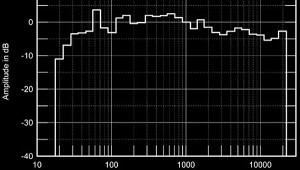
These principles were described in JA's computer simulations of the effects of different types and amounts of jitter in Vol.13 No.12; I've included three of his plots here. Fig.4 is a spectral analysis of a simulated DAC output when reproducing a full-scale, 10kHz sinewave with a jitter-free clock. Fig.5 is the same measurement, but with two nanoseconds (2ns or 2 billionths of a second) of white jitter added—note the higher noise floor. Fig.6 shows the effect of 2ns of jitter with a frequency of 1kHz. The last plot reveals the presence of discrete frequency sidebands on either side of the test signal caused by jitter of a specific frequency. The amplitude of these artifacts is a function of the input signal level and frequency; the higher the signal level and frequency, the higher the sideband amplitude in the analog output signal (footnote 2).

Fig.4 Audio-band spectrum of jitter-free 16-bit digital data representing a 10kHz sinewave at 0dBFS (linear frequency scale).

Fig.5 Audio-band spectrum of 16-bit digital data representing a 10kHz sinewave at 0dBFS afflicted with 2ns p-p of white-noise jitter (linear frequency scale). Note rise of approximately 12dB in the noise floor compared with fig.4, which represents a significant 2dB loss of signal resolution.
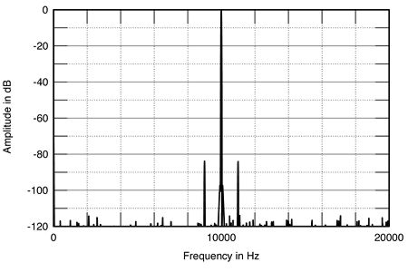
Fig.6 Audio-band spectrum of 16-bit digital data representing a 10kHz sinewave at 0dBFS afflicted with 2ns p-p of sinusoidal jitter at 1kHz (linear frequency scale). Note addition of sidebands at 9kHz and 11kHz compared with fig.4, though the noise floor remains at the 16-bit level.
How much jitter is audible? In theory, a 16-bit converter must have less than 100 picoseconds (ps) of clock jitter if the signal/noise ratio isn't to be compromised. (There are 1000ps in a nanosecond; 1000ns in a microsecond; 1000µs in a millisecond; and 1000ms in a second.) Twenty-bit conversion requires much greater accuracy, on the order of 8ps. 100ps is one-tenth of a billionth of a second (1/1010s), about the same amount of time it takes light to travel an inch. Moreover, this maximum allowable figure of 100ps assumes the jitter is random (white) in character, without a specific frequency which would be sonically less benign. Clearly, extraordinary precision is required for accurate conversion (see Sidebar).
Where does clock jitter originate? The primary source is the interface between a CD transport and a digital processor. The S/PDIF (Sony/Philips Digital Interface Format) signal that connects the two has the master clock signal embedded in it (it is more accurate to say the audio data are embedded in the clock). The digital processor recovers this clock signal at the input receiver chip (usually the Yamaha YM3623B, Philips SAA7274, or the new Crystal CS8412).
The typical method of separating the clock from the data and creating a new clock with a phase-locked loop (PLL) produces lots of jitter. In a standard implementation, the Yamaha chip produces a clock with 3-5 nanoseconds of jitter, about 30 to 50 times the 100ps requirement for accurate 16-bit conversion (the new Crystal CS8412 input receiver in its "C" incarnation reportedly has 150ps of clock jitter). Even if the clock is recovered with low jitter, just about everything inside a digital processor introduces clock jitter: noise from digital circuitry, processing by integrated circuits—even the inductance and capacitance of a printed circuit board trace will lead to jitter.
It's important to note that the only point where jitter matters is at the DAC's word-clock input. A clock that is recovered perfectly and degraded before it gets to the DAC is no better than a high-jitter recovery circuit that is protected from additional jitter on its way to the DAC. Conversely, a highly jittered clock can be cleaned up just before the DAC with no penalty (footnote 3).
Logic induced modulation (LIM)
There are two other significant sources of jitter in D/A converters. The first mechanism was recently discovered by Ed Meitner of Museatex and Robert Gendron, formerly a DAC designer at Analog Devices and now at Museatex. This jitter-inducing phenomenon, called Logic Induced Modulation (LIM), was discovered only after Meitner and Gendron invented a measurement system that revealed its existence. This measurement tool, called the LIM Detector, reveals not only how much clock jitter is present in a digital processor, but also displays its spectral distribution when connected to a spectrum analyzer or FFT machine. The jitter's spectral content—and whether or not it is random or composed of discrete frequencies—is much more important sonically than the overall amount of jitter. Two digital processors could each claim, say, 350ps of jitter, but the processor whose word clock was jittered at a specific frequency would likely suffer from a greater amount of sonic degradation than the other processor which had the same RMS level of random jitter. More on this later.
It's worth looking at Logic Induced Modulation in detail; the phenomenon is fascinating:
LIM is a mechanism by which the digital code representing an audio signal modulates (jitters) the clock signal. If a digital processor is driven by the code representing a 1kHz sinewave, the clock will be jittered at a frequency of 1kHz. Put in 10kHz, and jitter with a frequency of 10kHz will appear on the clock. Remember, jitter with a specific frequency is much more sonically pernicious than random-frequency jitter.
Here's how LIM is generated. In an integrated circuit (IC), there are many thousands of transistors running off the same +5V (usually) power-supply rail. When an IC is processing the code representing a 1kHz sinewave, for example, those thousands of transistors are turning on and off in a pattern repeating 1000 times per second. The current demands of all those transistors turning on together modulates the power-supply rail at the frequency of the audio signal. Just as the lights in a house dim momentarily when the refrigerator motor turns on, the +5V power-supply rail droops under sudden current demand from the chip's transistors. The analog audio signal thus appears on the IC's power-supply rail.
Now, the transition between a logic "0" and a logic "1" occurs at the leading edge of a squarewave. The precise point along the leading edge at which the circuit decides that a "1" is present is determined by the power-supply voltage reference. If that voltage fluctuates, the precise time along the leading edge at which the circuit recognizes a "1" will also fluctuate—in perfect synchronization with the power-supply voltage modulation. This uncertainty in the timing of the logic transitions induces jitter on the clock—at the same frequency as the audio signal the IC is processing. Put in the code representing 1kHz and the IC's power supply will be modulated at 1kHz, which in turn causes jitter on the clock at 1kHz. According to Meitner, it is possible to AC-couple a high-gain amplifier to the digital power-supply rail and hear the music the processor is decoding.
This astonishing phenomenon was discovered quite by accident after Meitner and Gendron designed the device to display the jitter's spectral distribution. When they put in a 1kHz digital signal, the jitter had a frequency of 1kHz with its associated harmonics. (footnote 4, footnote 5)
There is another mechanism by which clock jitter correlated with the audio signal is created. This phenomenon, described by Chris Dunn and Dr. Malcolm Hawksford in their paper presented at the Fall 1992 Audio Engineering Society convention (and alluded to in the Meitner/Gendron paper), occurs in the AES/EBU or S/PDIF interface between a transport and a digital processor. Specifically, they showed that when the interface is band-limited, clock jitter with the same frequency as the audio signal being transmitted is produced in the recovered clock at the digital processor. Although this phenomenon produces the same type of signal-correlated jitter as LIM, it is a completely different mechanism. A more complete discussion of Dunn's and Hawksford's significant paper [reprinted in Stereophile in March 1996 (Vol.19 No.3) as "Bits is Bits?"—Ed.] can be found in my AES convention report in next month's "Industry Update." (footnote 6)
Measuring clock jitter
Museatex has made the LIM Detector available to anyone who wants to buy one. Stereophile jumped at the chance (see Sidebar).
First, you have to open the processor's chassis and find the DAC's word-clock pin with a conventional oscilloscope and probe. The probe hooked up to the word-clock signal is then connected to the input of the LIMD and the LIMD is tuned to that word clock using preset frequency settings. To look at the spectrum of any processor's word clock (up to 20kHz), we fed the LIMD's analog output to our Audio Precision System One Dual Domain to create FFT-derived spectral analysis plots. A one-third-octave analyzer can also be used, though this gives less frequency resolution, of course. If the output of the LIMD is connected to an RMS-reading voltmeter, the overall jitter level can be read as an AC voltage. Knowing how many millivolts are equivalent to how many picoseconds of jitter—the LIMD output voltage also depends on the sampling frequency—allows the jitter to be easily calculated.
The measurements of digital-processor clock jitter included in this article thus include the processor's overall jitter level expressed in picoseconds and a plot of the jitter's spectral distribution. The latter is scaled according to the RMS level—0dB is equivalent to 226.7ns of jitter—so that spectra for different processors can be readily compared.
Before getting to the measurement results, a quick description of how the LIMD works is useful. Like all brilliant inventions, the technique is simple and obvious—after you've been told how it works.
A jittered clock can be considered as a constant carrier signal which has been frequency-modulated (FM). The jitter components can therefore be separated from the clock by an FM demodulator—just like those found in all FM tuners. In the LIMD, once it has been correctly tuned to the word-clock frequency, an FM demodulator removes the clock signal, leaving only the audio-band jitter components—which can be measured as a voltage or output for spectral analysis.
I have no doubt that many manufacturers of the digital processors tested for this article will question the test methodology and results. Some claim extraordinarily low jitter in their products—claims that were not confirmed by my measurements. This disparity can arise because there is no standard method of measuring jitter. When I'm told by a manufacturer that his product has "less than 70ps of jitter," my first question is, "How do you measure 70ps?" The response is often less than adequate: "We calculate it mathematically" is a common reply. Moreover, some jitter measurements attempt to measure jitter indirectly—as a function of the rise in the noise floor, for example—rather than looking directly at the word clock.
At any rate, if the absolute levels presented in this article are in error, the relative differences between processors will still be correct. If anyone can demonstrate a better method of measuring jitter, I'm all ears.
Footnote 2: The accuracy of these simulations was confirmed by Chris Dunn and Malcolm Hawksford in their AES paper "Is the AES EBU/SPDIF Digital Audio Interface Flawed?," presented at the 93rd AES convention. Copies of individual papers are available for $3 each from the Audio Engineering Society, 60 East 42nd St., New York, NY 10165-2520. Ask for preprint #3360 (C-1).—Robert Harley
Fig.30 Jitter Spectrum, Bitwise System Zero processing 1kHz squarewave at 0dBFS via Toslink optical datalink (linear frequency scale, 0dB = 226.8ns). Note significant increase in level of data-related, odd-harmonic jitter components with the lower-bandwidth data connection.
Footnote 4: Meitner and Gendron presented a paper at the 91st AES convention called "Time Distortions Within Digital Audio Equipment Due to Integrated Circuit Logic Induced Modulation." See footnote 2 for ordering information.—Robert Harley
Footnote 5: To say this is astonishing is an understatement. When Bob and I first looked at the spectrum of the word-clock jitter in a particularly poor-sounding D/A processor when it was fed the digital code representing a 1kHz sinewave and found a strong 1kHz component, we were flabbergasted. Our flabber was even more gasted when we changed the frequency represented by the code and found the jitter component to change accordingly.—John Atkinson
Footnote 6: This is the same paper referenced in footnote 1.—Robert Harley
NEXT: Page 3 »
|
| |||||||||
- Log in or register to post comments


| Loudspeakers Amplification Digital Sources | Analog Sources Accessories Featured | Music Columns Retired Columns | Show Reports | Features Latest News Community | Resources Subscriptions |
 © 2024 Stereophile
AVTech Media Americas Inc., USA
All rights reserved

