| Columns Retired Columns & Blogs |
Expressive Technologies SU-1 moving-coil step-up transformer Measurements
Sidebar 3: Measurements
Footnote 1: The relationship between inductive reactance (a force which opposes current) and frequency is stated in the formula XL=2pifL. This relationship is linear; double the frequency and the inductive reactance doubles. At DC (0Hz) there is no reactance and the source sees only the DC resistance of the transformer primary.
When I measured the SU-1, the results appeared to be more related to the test setup than the SU-1's intrinsic performance. Just as there was a large variability in sound quality depending on the phono preamp used, the measurement results were highly dependent on the test conditions.
I initially measured significant rolloffs at the audio-band frequency extremes—down 2dB at 20kHz and nearly 3dB at 20Hz. These rolloffs would be highly audible, yet no rolloff was suggested by my auditioning. The cause of the measured rolloff was twofold. The 25 ohm source impedance (the lowest possible setting) of the Audio Precision System One's signal generator formed a voltage divider with the SU-1's 75 ohm input impedance. Because the transformer inductive reactance presents a much lower impedance at low frequencies, more and more of the voltage is dropped across the source impedance as frequency decreases instead of across the transformer input. Hence the bass rolloff (footnote 1).
The AP System One's relatively high output impedance (compared to a low-output moving-coil, typically less than three ohms and sometimes a few tenths of an ohm for the ultra-low output types) was also responsible for the treble rolloff. A transformer's output impedance is a function of the source impedance driving the primary and the transformer's turns ratio. Specifically, the transformer's output impedance is equal to the square of the turns ratio multiplied by the source impedance. With a source impedance of 25 ohms (the System One's generator), and the SU-1's 25:1 turns ratio, the output impedance thus becomes very high (nearly 16k ohms). Further, the capacitance the secondary winding drives is also a function of the input capacitance: the source and interconnect capacitance are also multiplied by the square of the turns ratio. A few hundred pF at the input results (in the SU-1's case of a 25:1 turns ratio) in several tens of ;uF the output must drive. This high output impedance and high capacitance form an RC filter across the output, dropping high frequencies across the RC network instead of across the load, and rolling off the treble (even with the System One's 100k ohms input impedance).
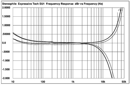
JA remeasured the transformer, driving it with the Krell KBL line-level preamplifier to get a low enough source impedance (2.2 ohms), though this does make the test signal a little noisy. His frequency response, taken at 5mV input, is shown in fig.1. The solid lines are the left channel; the dashed, the right channel. To show the effect of load impedance, JA used the Audio Precision's inputs set to 600 ohms—the curves that droop above 4kHz—and 100k ohms—the curves that peak above 50kHz, reaching about +8dB. (Into the lower load, of course, the absolute level dropped by 10dB or so.) The measured voltage gain at 1kHz into the 100k load was almost exactly the specified 28dB.
Fig.1 suggests that the SU-1's balance will be highly dependent on the associated components, primarily the cartridge's output impedance, the interconnect capacitance, and the phono stage input impedance. Indeed, this was suggested by the auditioning. Potential purchasers are advised to audition the SU-1 in their own systems before making a buying decision. Basic guidelines, however, can be offered. The SU-1 will work best with low-output moving-coil cartridges (both because of their low output impedance and need for higher gain) and 47k ohm input impedance moving-magnet phono stages. The combination of the AudioQuest 7000 cartridge (0.3mV output and 2.5 ohms output impedance) and the SP11's 47k ohm input impedance was a good match for the SU-1. (The Lyra Clavis and Parnassus have an output impedance of less than 1 ohm and may benefit even more from the SU-1.)
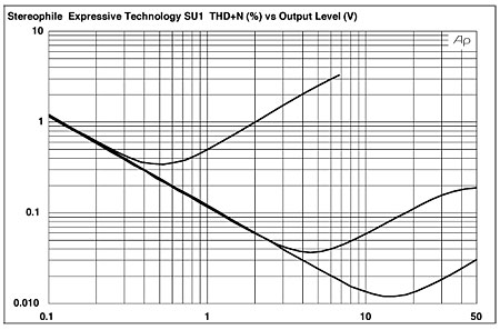
The putative Achilles' heel of step-up transformers is their distortion and overload characteristic. Well, the SU-1 proved exceptional in this regard. Fig.2 shows the THD+noise in the transformer's output for output levels ranging from 0.1V to 50V, equivalent to input levels of 4mV to 2V. The three curves shown are for 20Hz (top), 20kHz (middle), and 1kHz (bottom): in all three cases, the sloping curve from left to right represents the system's noise floor; as the signal rises, the slope down eventually changes to a slope up, indicating that the distortion products have risen above the noise. At 1kHz, you can see that this change happens at a whopping 15V output, equivalent to an input of 600mV. With reference to the standard MC output of 0.5mV, this is equal to an overload margin of 61.6dB! The phono stage input will clip long before the SU-1. Even at the frequency extremes, the "bend" in the THD characteristic occurs at very high input levels, equivalent to margins of 44dB at 20Hz and 31dB at 20kHz. (The reduced margin at 20kHz is due to the RIAA curve pre-emphasizing this frequency on the LP by almost 20dB compared with the level at 1kHz. This factor also makes the reduced margin of the transformer at very low recorded frequencies less of a problem, though it must be remembered that warp information comes through at full level.)
The final graph (fig.3) shows the manner in which the distortion changes with frequency. To get sensible readings above the noise floor, I drove the transformer with a 100mV signal. Somewhat surprisingly, the left-channel distortion in the bass region was higher than the right-, though at the kind of low-frequency levels typical of an MC cartridge, there won't be any distortion! The left channel also shows a slight but still negligible rise in distortion above 25kHz. The flat curves in the center represent the distortion in this region dropping below the noise floor.—Robert Harley

Footnote 1: The relationship between inductive reactance (a force which opposes current) and frequency is stated in the formula XL=2pifL. This relationship is linear; double the frequency and the inductive reactance doubles. At DC (0Hz) there is no reactance and the source sees only the DC resistance of the transformer primary.
|
| ||||||||||
- Log in or register to post comments


| Loudspeakers Amplification Digital Sources | Analog Sources Accessories Featured | Music Columns Retired Columns | Show Reports | Features Latest News Community | Resources Subscriptions |
 © 2024 Stereophile
AVTech Media Americas Inc., USA
All rights reserved

