| Columns Retired Columns & Blogs |
DK Designs VS.1 Reference Mk.III integrated amplifier Measurements
Sidebar 3: Measurements
Before performing any measurements on it, I preconditioned the DK Designs VS.1 Reference Mk.III by running it at 50Wpc (one-third the specified power) with both channels driven into 8 ohms for 60 minutes. The THD+noise remained at a highish 0.2% throughout this period, after which the heatsinks on the amplifier's sides measured around 55°C. The front third of the heatsinks remained cool, however, as no active devices are attached to these.
The fact that the phono stage has its own output, usually connected by jumpers to the Aux 1 line input, enabled me to look at its performance in detail. The phono input preserved absolute polarity (ie, was noninverting). The input impedance was higher than the specified 47k ohms over most of the audioband, at 97k ohms, though this dropped to 43k ohms at 20kHz. The voltage gain was 37.9dB, suggesting that the input is optimized for high-output moving-magnet cartridges. Reinforcing this impression was the phono stage's superb overload margins: no less than 28dB in the bass and midrange, and even 27.35dB at 20kHz (all figures ref. 5mV at 1kHz).
Channel separation was better than 80dB above 2kHz. The phono input's signal/noise ratio was 52.2dB (again ref. 5mV input at 1kHz) with a wideband, unweighted measurement. Switching in an A-weighting filter increased this to a good 79.4dB. The RIAA error (fig.1) suffered from a mild boost through the bass and a slightly rising response above the audioband. The former will be audible, the latter not. Distortion was very low, though the spectrum of a 1kHz tone at 13mV input (fig.2) had some fifth harmonic present at the same low level of the second harmonic (–90dB, 0.003%). The phono stage's output impedance was a moderately low 445 ohms at all audio frequencies.
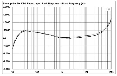
Fig.1 DK Designs VS.1 Reference Mk.III, phono-input RIAA error (0.5dB/vertical div.).
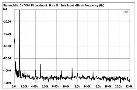
Fig.2 DK Designs VS.1 Reference Mk.III, spectrum of 1kHz sinewave, DC–10kHz, at 13mV input level (linear frequency scale).
Turning to the VS.1's line and power-amplifier sections, the amplifier's maximum voltage gain was high through its RCA line inputs, at 48.9dB into 8 ohms. Peculiarly, the gain through the balanced XLR input was 12dB lower. Both this and the preceding figure changed very slightly whenever the level of the input signal was changed, suggesting some marginal instability. Both the RCA and XLR inputs inverted signal polarity, the latter driven with pin 2 hot. The input impedance of the unbalanced RCA jacks was lower than specified at 23.4k ohms at 1kHz, this rising to 31k ohms at the upper and lower edges of the audioband.
The right channel's output impedance was moderate for a solid-state design, at 0.12 ohm at 20Hz and 1kHz, this rising slightly to 0.16 ohm at 20kHz. The left channel's output impedance was twice this figure, suggesting some QA problems, and gave rise to ±0.2dB response variations with our standard simulated loudspeaker (fig.3, top trace at 2kHz). This graph also shows a channel imbalance of 0.25dB and a fairly quick ultrasonic rolloff, with the amplifier's output down 0.25dB into 8 ohms at 20kHz and its –3dB point at 64kHz, resulting in a 10kHz squarewave response with rounded leading edges (fig.4). This will not be enough to correlate with BJR's finding the amplifier's highs to lack air, however. Fig.3 was taken with an unbalanced input and with the volume control at 12:00; increasing it to its maximum setting and replotting the frequency response at the same output level gave a 0.5dB channel imbalance in the opposite direction—ie, the right channel is now louder than the left—and the –3dB point moved up to 116kHz (not shown). Driving the amplifier via its balanced input, again with the volume control at its maximum setting, revealed a 1dB difference in channel gain, this time in favor of the left channel.

Fig.3 DK Designs VS.1 Reference Mk.III, frequency response at 2.83V into (from top to bottom at 2kHz): simulated loudspeaker load, 8, 4, 2 ohms (0.5dB/vertical div., right channel dashed).

Fig.4 DK Designs VS.1 Reference Mk.III, small-signal 10kHz squarewave into 8 ohms.
Measuring the crosstalk was complicated by the VS.1's sensitivity to the grounding arrangement between the amplifier and my Audio Precision System One test set. When the grounding was optimal, channel separation via the unbalanced inputs was better than 65dB below 1kHz, but suffered from capacitive coupling, reducing the separation to 40dB at 20kHz (fig.5). The S/N ratio (ref. 2.83V into 8 ohms), taken with the unbalanced input shorted and the volume control at its maximum, was moderate at 63.8dB, wideband, unweighted, this increasing slightly to 70.2dB when A-weighted.

Fig.5 DK Designs VS.1 Reference Mk.III, line-input channel separation (10dB/vertical div.).
The VS.1's preamp tubes are somewhat microphonic—tapping the glass envelopes with a pencil gave an easily measurable signal at the amplifier's output. However, any audible effects should be minimized by the facts that the tubes are shielded by the top cover—the mesh openings in the cover actually go over the transformers and there is an internal wall between the tube circuit and the transformers.
Fig.6 shows how the THD+noise percentage in the VS.1's output varied with output power. The VS.1 more than meets its power specification, with a measured clipping level of 205W/23.1dBW into 8 ohms and 330W/22.2dBw into 4 ohms, both channels driven. Into 2 ohms with one channel driven, the amplifier gave out 500W (21dBW)!

Fig.6 DK Designs VS.1 Reference Mk.III, distortion (%)vs 1kHz continuous output power into (from bottom to top at 100W): 8, 4, 2 ohms.
The rise in THD+N above a couple of watts' output in fig.6 suggests the VS.1 is a low-negative-feedback design. I measured how the THD+N percentage changed with frequency at 5V output, a level that fig.6 suggests is where the distortion is just starting to rise above the background noise. The results are shown in fig.7: the left and right channels are different, the right channel either less noisy or more linear over most of the audioband. Above 10kHz, however, both channels show the same rise in THD, presumably due to the circuit's restricted open-loop gain-bandwidth product.

Fig.7 DK Designs VS.1 Reference Mk.III, THD+N (%)vs frequency at 5V into (from bottom to top at 10kHz): 8, 4, 2 ohms.
At small-signal levels, the VS.1's distortion is predominantly second-harmonic (fig.8), though a discontinuity can be seen at the negative–positive half-cycle zero crossing point. This behavior suggests an inadequate output-stage bias, especially as it disappears at higher output levels, where the only significant harmonics that can be seen are the second and third (fig.9), which will ameliorate their rather high level. The DK amplifier stumbled a little on the grueling HF intermodulation test (fig.10), an equal mix of 19kHz and 20kHz tones at a level just below visible clipping on the oscilloscope screen producing a 1kHz difference tone at –56dB (0.15%). Note also the appearance of ±120Hz sidebands to either side of the main spectral lines in this graph, as well as the beginning of some noise modulation. The amplifier is obviously working hard under these conditions.

Fig.8 DK Designs VS.1 Reference Mk.III, 1kHz waveform at 1W into 8 ohms (top), 0.042% THD+N; distortion and noise waveform with fundamental notched out (bottom, not to scale).

Fig.9 DK Designs VS.1 Reference Mk.III, spectrum of 50Hz sinewave, DC–1kHz, at 100W into 4 ohms (linear frequency scale).

Fig.10 DK Designs VS.1 Reference Mk.III, HF intermodulation spectrum, DC–24kHz, 19+20kHz at 180W peak into 4 ohms (linear frequency scale).
The DK Designs VS.1 Reference Mk.III offers a lot of power in a relatively compact package, and has a bombproof phono stage. However, I was somewhat bothered by the measured differences between its two line-input channels and by its slightly unstable gain.—John Atkinson
|
| ||||||||||
- Log in or register to post comments


| Loudspeakers Amplification Digital Sources | Analog Sources Accessories Featured | Music Columns Retired Columns | Show Reports | Features Latest News Community | Resources Subscriptions |
 © 2024 Stereophile
AVTech Media Americas Inc., USA
All rights reserved

