| Columns Retired Columns & Blogs |
Canon S-35 loudspeaker Measurements
Sidebar 3: Measurements
Footnote 1: For my in-room spectral analyses, I average six measurements at each of 10 separate microphone positions for left and right speakers individually, giving a total of 120 original spectra. These are then averaged to give a curve which in my room has proved to give a good correlation with a loudspeaker's perceived balance. I use an Audio Control Industrial SA-3050A spectrum analyzer with its own microphone, which acts as a check on the MLSSA measurements made with the B&K mike. I also used the Goldline DSP-30 automated spectrum analyzer.—John Atkinson
Other than impedance, for which I used an Audio Precision System One, all the measurements were performed with a MLSSA system (v.8.5) from DRA Labs, in combination with an Outline computer-controlled loudspeaker turntable and a B&K 4006 microphone calibrated to be flat on-axis at the typical measuring distance I use. To minimize reflections from the test setup, the measuring microphone is flush-mounted inside the end of a long tube. Reflections of the speaker's sound from the mike stand and its hardware will thus be sufficiently delayed not to affect the measurement.
At an estimated 85dB/W/m (B-weighted), the S-35 is quite sensitive for such a small speaker. (In-room, this will appear greater due to the design's wide dispersion.) Its plot of impedance magnitude and phase (fig.1) reveals it to be a moderately easy load for an amplifier to drive, dropping below 6 ohms only in the lower midrange and above 13kHz. Judging from the impedance minimum at 70Hz, that's the tuning frequency of the twin ports, suggesting only moderate low-frequency extension. The slight wrinkle in the magnitude trace between 350Hz and 400Hz suggest the presence of a cabinet resonance of some kind at that frequency.
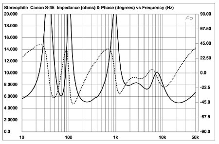
Fig.1 Canon S-35, electrical impedance (solid) and phase (dashed) (2 ohms/vertical div.).
Fig.2 includes quite a lot of information. From 300Hz upward, the trace is the anechoic response of the S-35 at a 50" microphone distance, averaged across a 30° horizontal window on an axis level with the "lip" of the S-35's hemispherical woofer enclosure. Though it looks a little ragged, the response is basically flat from 300Hz to 4kHz, the bumps being balanced by dips. A deep suckout appears at 5kHz, however, and higher in frequency the tweeter is a little "hot," averaging 5dB higher than the 1kHz reference level from 7kHz to 22kHz.
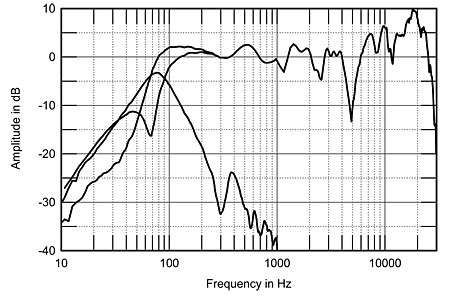
Fig.2 Canon S-35, anechoic response on central "lip" axis at 50", averaged across 30° horizontal window and corrected for microphone response, with nearfield woofer and port responses plotted below 300Hz and 1kHz, respectively, and complex sum of woofer and port responses plotted below 300Hz (top at 100Hz).
The three traces to the left of fig.2 are (from bottom to top just above the woofer's minimum-motion point of 68Hz): the woofer's nearfield response; the port's nearfield response; and the complex sum (amplitude and phase) of the woofer and port outputs, with the two proportioned in the ratio of the square roots of their areas. The overall response peaks up by 2dB or so in the upper bass before beginning its 24dB/octave acoustic rollout below 90Hz. The –6dB point lay at a reasonably low 65Hz, though, as I found in my auditioning, placing the speakers close to the boundary behind them was essential to getting the 4"-diameter woofer cones to produce some slam.
Remember the impedance wrinkle just below 400Hz? Probably not coincidentally, a peak appears in the port output at the same frequency. It's over 20dB down, so the subjective effect will probably be minimal unless the cabinet also sings at the same frequency.
Fig.3 shows the Canon's horizontal dispersion, with the on-axis response subtracted from each trace. Though the speaker is a little more directional in the midrange than we usually see, the S-35 does indeed feature a very wide dispersion throughout the treble. The ridges and valleys apparent in this diagram are due to the dips and peaks apparent in the on-axis response (fig.2) to some extent filling in/flattening out to the speaker's sides. Only in the very top octave is the speaker quite directional, but even then the axial output is maintained to at least 45° off-axis. Negishi-san's Wide-Imaging Stereo acoustic-mirror concept appears to work.
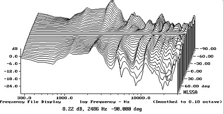
Fig.3 Canon S-35, horizontal response family at 50", normalized to response on central axis, from back to front: differences in response 90°–5° off-axis; reference response; differences in response 5°–90° off-axis.
Vertically (fig.4), as might be expected from its drive-unit layout, the treble falls off if you sit much below the "lip," and rapidly shelves down if you sit even a little above the loudspeaker—as I found in my auditioning. In my listening room, the spatially averaged response (footnote 1) in free space (fig.5) was helped a little bit by a room mode to stay flat down to the 63Hz 1/3-octave band. An excess of energy in the low treble might correlate with the nasal quality I heard, while the suckout at 5kHz was omnipresent in the listening room. The top octave is indeed somewhat exaggerated, this tying in with the sniffy character I noticed on sibilance.
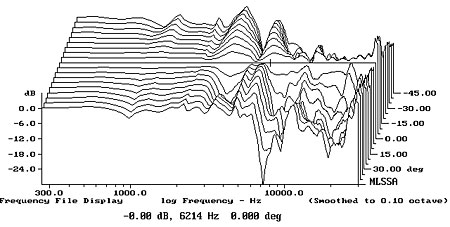
Fig.4 Canon S-35, vertical response family at 50", normalized to response on central axis, from back to front: differences in response 45°–5° above central axis; reference response; differences in response 5°–45° below central axis.
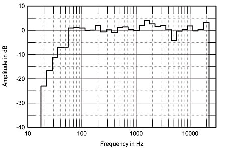
Fig.5 Canon S-35, spatially averaged 1/3-octave response in JA's listening room.
In the time domain, the S-35's step response (fig.6) is a little hard to interpret. What we appear to see is a slow rise from the midrange/woofer, followed about 0.2ms later by a sharp up/down spike from the tweeter. What would otherwise be a relatively good triangle step shape is broken up by reflections. The cumulative spectral-decay, or waterfall, plot calculated from the impulse response data (fig.7) has some areas of clean decay, but a quite severe resonant ridge at 3kHz is very likely associated with the nasal coloration I noted, especially as there are a dip and another peak in the octave below. That the suckout at 5kHz in the response graphs is due to interference is suggested by the fact that the energy at this frequency returns after about 1ms in the waterfall plot. The fact that the initial arrivals of the woofer and tweeter outputs are separated by 0.2ms, the period of a 5kHz tone, is a suitable smoking gun.
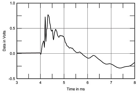
Fig.6 Canon S-35, step response on tweeter axis at 50" (5ms time window, 30kHz bandwidth).
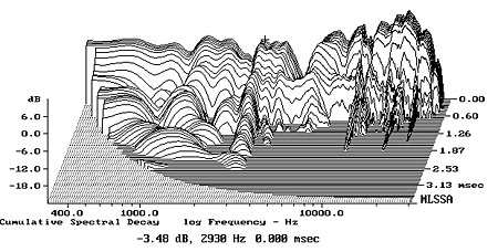
Fig.7 Canon S-35, cumulative spectral-decay plot at 50" (0.15ms risetime).
Remember the peak in the port output at 380Hz and the wrinkle in the impedance plot at the same frequency? Fig.8 shows a waterfall plot calculated from the output of a simple PVDF ribbon accelerometer wrapped from side to side across the top of the woofer dome. There's indeed a resonant mode apparent at that frequency (the cursor position), but other strong modes can be seen at 170Hz, 290Hz, and 1400Hz. Though none is that high in level, the modes at 290Hz and (particularly) 380Hz could be readily heard with a stethoscope on all the enclosure surfaces, adding a hooty overhang as a sinewave tone swept though their frequencies. I wasn't aware of any subjective consequence at the listening position, other than a degree of thickening on male voice, but I did notice a degree of midrange congestion and hardness when the speaker was driven to high levels, perhaps due to these modes making their presence known.—John Atkinson
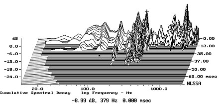
Fig.8 Canon S-35, cumulative spectral-decay plot of accelerometer output fastened to the top of the woofer dome (MLS driving voltage to speaker, 7.55V; measurement bandwidth, 2kHz).
Footnote 1: For my in-room spectral analyses, I average six measurements at each of 10 separate microphone positions for left and right speakers individually, giving a total of 120 original spectra. These are then averaged to give a curve which in my room has proved to give a good correlation with a loudspeaker's perceived balance. I use an Audio Control Industrial SA-3050A spectrum analyzer with its own microphone, which acts as a check on the MLSSA measurements made with the B&K mike. I also used the Goldline DSP-30 automated spectrum analyzer.—John Atkinson
|
|
| ||||||||||
- Log in or register to post comments


| Loudspeakers Amplification Digital Sources | Analog Sources Accessories Featured | Music Columns Retired Columns | Show Reports | Features Latest News Community | Resources Subscriptions |
 © 2024 Stereophile
AVTech Media Americas Inc., USA
All rights reserved

