| Columns Retired Columns & Blogs |
Bad Vibes! Sidebar 2
Fundamentals of Isolating Suspensions
In Sidebar 1, I explained, graphically, how the resonant frequencies of a solid structure relate to its modal activity when stimulated by vibrations. It is apparent that, regardless of which method of rigid coupling, damping, or a combination thereof is used to minimize the negative impact of vibration on a platform, stand, or component, the best one can achieve through these means alone is a reduction in amplitude approximating the ideal rigid body line.
In Sidebar 1, I explained, graphically, how the resonant frequencies of a solid structure relate to its modal activity when stimulated by vibrations. It is apparent that, regardless of which method of rigid coupling, damping, or a combination thereof is used to minimize the negative impact of vibration on a platform, stand, or component, the best one can achieve through these means alone is a reduction in amplitude approximating the ideal rigid body line.
To further reduce the impact of vibration, we must isolate any rigid structure from outside sources of resonant excitation. Isolation systems are evaluated through two models: The Simple Harmonic Oscillator, consisting of a rigid mass connected to the floor or supporting element by a linear spring (fig.1), forms a suspension that has no applied damping to dissipate mechanical energy. Every suspension has a natural resonant frequency determined by the supported mass and the spring compliance. It decreases for a heavier mass and/or a more compliant (softer) spring. Theoretically, the peak displacement caused by the excitation of a truly undamped harmonic oscillator's resonant frequency is infinite (fig.2).
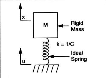
Fig.1 Simple Harmonic Oscillator. Graphic courtesy Newport Corporation.

Fig.2 Transmissibility of Simple Harmonic Oscillator. Note that without damping, amplification at the resonant peak would be infinite! Graphic courtesy Newport Corporation.
The Damped Harmonic Oscillator is the same, with the addition of a damping mechanism to reduce the amplitude of displacement (fig.3). As damping increases, the amplitude at resonance decreases. However, the "rolloff" rate at higher frequencies also flattens out, meaning that the decline in the transmissibility of vibration occurs more slowly. Since the theoretical Simple Harmonic Oscillator does not exist in the real world, all practical systems are some variation of the damped suspension model (fig.4).

Fig.3 Damped Harmonic Oscillator. Graphic courtesy Newport Corporation.
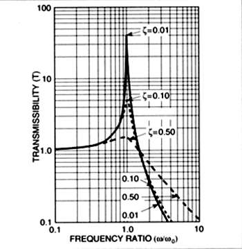
Fig.4 Transmissibility of Damped Harmonic Oscillator. Note that as damping increases, the amplitude at resonance decreases and the rate of vibration attenuation below resonance declines. Graphic courtesy Newport Corporation.
Since isolation only begins at a frequency near 1.4 times the resonant frequency of a suspension---at best---it is important to push this frequency as low as possible, while maintaining stability. A transmissibility curve is a method used for evaluating the performance of an isolation system. Transmissibility is the ratio of the amplitude of vibrations transmitted through an isolator to that of the driving force. The Y axis of the log-log graph defines the amount of vibration transmitted through the suspension. The baseline, represented by the line at unity (1), corresponds to transmission of 100% of the vibration inherent in the structure supporting the suspension. (Note that it is also roughly analogous to the ideal rigid body line on a solid structure's displacement curve, as shown in sidebar 1, in that any deviation from the ideal rigid body line occurs above this baseline.) The X axis shows frequency and, combined with the Y axis (transmissibility), defines the system's resonant frequency, the height and breadth of its corresponding zone of amplification, and the amount of attenuation for any frequency beyond the amplification zone. The figures are fairly self-explanatory.
Keep in mind that all forms of rigid coupling using cones or damping techniques will either increase or decrease the amplitude of any given resonant frequency band only above the baseline represented by 1! Level 10 on the Y axis equals 1000% amplification of baseline vibrations, and 0.1 equals a 90% reduction in transmission of the same to the isolated components. The curve is asymptotic, so 0.01 equals 99% reduction, 0.001 is equivalent to 99.9% reduction in transmissibility, and so forth. 100% isolation is, of course, never reached..
Fig.5 shows transmissibility curves showing actual measured performance for a typical high-quality pneumatic isolation system in both the horizontal and vertical planes. Note the near-equal performance in both planes, the suspension's very low, well-damped resonant frequency, and its steep 12dB/octave rolloff.---Shannon Dickson
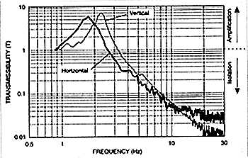
Fig.5 Transmissibility of a high-quality pneumatic suspension in horizontal (dark curve) and vertical planes. The actual vibration isolation at 10Hz is approximately 95% in both planes! Graphic courtesy Newport Corporation.
|
| |||||||||
- Log in or register to post comments


| Loudspeakers Amplification Digital Sources | Analog Sources Accessories Featured | Music Columns Retired Columns | Show Reports | Features Latest News Community | Resources Subscriptions |
 © 2024 Stereophile
AVTech Media Americas Inc., USA
All rights reserved

