| Columns Retired Columns & Blogs |
Aunt Corey's Homemade Buffered Passive Preamplifier Letters
Letters in response appeared in Vol.15 No.2, February 1992
Passive semantics
Editor:
My audiophile interest and activity date back to the time when a cactus thorn was the high-end stylus of choice, ca 1938. This predates the preamplifier by approximately ten years.
In its first embodiment, a preamp was just that: a self-powered extra stage of amplification between the phono cartridge and whatever amplifier was being used. This was made necessary by the very low voltage output of GE's new variable reluctance cartridge as it began to replace the crystal devices we had previously been using; no switches, no controls whatsoever.
Unfortunately my formal training in English goes back even farther so I don't know if the term is a mixed metaphor, hyperbole, a split infinitive, or what? But one thing's for sure. Corey Greenberg's device ain't a preamp.
---Charles N. Menz Troy, NY
Buffers & control units
Editor:
May I commend you for Corey Greenberg's article in the November 1991 issue? Great!
It was most interesting to me, for I have been using a buffered "passive preamp" for the last couple of years. It seemed an obvious thing to play with a high-impedance input and a low-impedance output design, and I am most satisfied.
I would like to try the Greenberg design, but the problem arises if one wants to purchase only a few pieces of BUF-03AJ, and the question of a suitable pot causes lots of heartaches.
I used a "Noble" pot (dual 100k), for I was able to obtain a few from a cooperative OEM. The Alps pots were available to my specification in lots of a few hundred only, so I had to forgo them. I later got a Penny & Giles dual rotary pot and, while expensive, it is great. The Noble and Alps are carbon, while the Penny & Giles is conductive plastic. Nevertheless, the carbon pots are quiet, and they do track beautifully.
As for the buffer, I tried the National LH0002, but finally adopted a circuit developed by Walt Jung, using discrete components, and I have enclosed a circuit of that buffer. As the transistors are specced at an "ft" of 300MHz, the slew is remarkably fast. I matched the pairs (Q1 & Q2 and Q3 & Q4) for "hfe" at a number of currents within the spec of up to 300mA. Mr. Jung said he just included the 10 ohm resistors as a precaution. As the input bases reflect the emitter-follower impedance, the input does not load the pot. The output is capable of driving any interconnect I have run across. In my humble opinion, the sound is great.
---L. B. Dalzell El Cajon, CA
Buffers & Analog Devices
Editor:
I read with great interest Corey Greenberg's article on Passive Preamp Design. It was partly because we are the proud manufacturer of the BUF-03 buffer amplifier chip that was mentioned, but mostly because I am, as many of us at Analog Devices are (yes, PMI is a division of Analog Devices, Inc.), audio enthusiasts, as evidenced by our company's line of high-performance and professional audio IC products. From a sonic quality perspective, there is not one here who disagrees with Corey's observation of how clean the BUF-03 amplifier sounds. Furthermore, I am in total agreement that, as power amplifiers are placed farther and farther away from the preamplifiers, the preamps will have a harder time driving long cables without losing high-end fidelity.
However, one point in the article on which I am compelled to comment is the suggested supply voltages of ±18V that power the BUF-03. We at Analog Devices/PMI do not recommend continuously operating the BUF-03's supply at ±18V, which is clearly specified in the data sheet as the device's absolute maximum rating. It is advisable to roll the supply voltages back to the recommended nominal ±15V. Doing so will not degrade the sound quality or the performance of the buffer. Besides, most power amplifiers peak out at line inputs of about 2V RMS [around 6V p-p---Ed.] anyway. The BUF-03 can easily handle more than three times this level of signal while operating at ±15V, so headroom should not be an issue.
A more important reason for rolling the supply voltages back is to reduce the amplifier's heat dissipation to a level that it was designed for---and therefore preserve its operating reliability. As Corey Greenberg had suggested, the BUF-03 is internally biased for class-A operation. It was designed to operate on relatively high stage current in order to get gobs of slew rate and bandwidth while keeping distortion low. As such, it runs hot to the touch even at the nominal ±15V.
Still another reason relating to the reliability is that by setting the power supply at the rated limit of ±18V, it does not allow for any supply-voltage tolerance. Most supplies can vary ±5% due to line-voltage variations, resistor tolerances, and load regulation changes, etc. This means there is a good chance the total supply's absolute maximum rating can be exceeded by 1.8V. Doing so can degrade the long-term reliability of the amplifier. In the case of the BUF-03, it is critical, not just because of the possibility of internal junction-voltage breakdown; more importantly, the additional power dissipation can heat the chip temperature beyond the maximum allowable limit, potentially destroying the device.
A quick calculation shows the BUF-03 must dissipate some 0.9W at ±18V supply at a worst-case supply current of 25mA. Unless the heatsink has a thermal resistance better than 100 degrees C/W, and the construction technique is nothing short of perfect, the chip's internal temperature rise will hover around its maximum allowable junction temperature of 175 degrees C. Thus the design allows no safety margin for temperature rise from room ambient or equipment enclosure. Worse yet, it leaves no reserve for additional power dissipation for driving the cable capacitance---which is not insignificant with a long line.
For these reasons it is advisable that the power-supply voltages be reduced to ±15V. This can be accomplished by changing the power-supply scaling resistors R2 and R4 from 12.9k to 10.5k (fig.1 schematic in article). Even with this modification, it is still a good idea to heatsink (better than 30 degrees C/W thermal resistance) the device as Corey suggested. Doing so assures ample reserve for driving any power amplifier, and many years of listening pleasure.
---James Wong Applications Engineering Manager, PMI Division, Analog Devices, Inc.
Buffers & power supplies
Editor:
Corey Greenberg's "buffered passive" preamp (Stereophile, November 1991) is a worthwhile project for the audio do-it-yourselfer in search of a high-performance, no-frills preamp design. The comments below are meant constructively, to maximize the potential long-term rewards for those audio hobbyists considering the project.
To those commenting on my ±12-±18V power-supply circuit and the use with the BUF-03 buffer IC, some remarks may be helpful, and are noted below. Readers are advised that I have no commercial interest with this circuit design. Technical questions on Linear Technology ICs can be directed to Rich Markell at (408) 432-1900 (my co-designer of the original circuit while at LTC).
The use of an apparently overdesigned transformer has benefits other than just sheer design conservatism (see the comments within Gary Galo's article in The Audio Amateur, 4/90, pp.47-48). The original prototype transformer that I used for the design was a Plitron (formerly ILP) PN 4A013, purchased from Active electronics for about $40. Later on, variants of this supply have been built successfully with the abundant 20/20VAC at 5A toroidals available from various surplus houses (Fair Radio, etc.). These can be had for about $10, but their use will require more careful heatsinking of the IC regulators...you should understand these factors before using one of these higher-output transformers. Note that the 4A013 transformer (or equivalent) will allow a ±15V supply to operate down to less than 110VAC input before dropout (when loaded with about 100mA DC).
A CAVEAT ON USING THE BUF-03 WITH HIGH SUPPLIES: Operation of this IC at ±18V may not be the best for long-term reliability, as it will dissipate excessive heat (even with a heatsink). Also, ±18V is also right at the maximum specification for the IC. Dropping the voltages to ±15V (with R2 & R4 = 10.5k as per the TAA schematic) will be more conservative, and heatsinking can still be retained at these voltages. Hopefully, these steps will allow users to get the most from this useful circuit.
---Walt Jung via The Audiophile Network
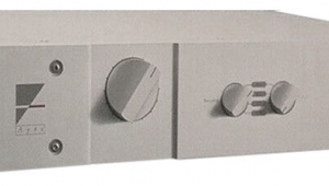
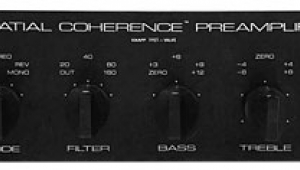
Regarding Corey's decision to run the BUF-03 chips at their maximum rated supply voltages is one of those things that is a good idea if it works, a bad idea if it doesn't. In his AMP-01 preamplifier design that I commissioned from electronics wiz Ben Duncan and that appeared in the UK magazine Hi-Fi News & Record Review in its May through November 1984 issues, the BUF-03s ran very hot even with what might be thought adequate heatsinking, but sounded superb on what I understood were ±18V voltage rails. My thanks to James Wong and Walt Jung for their sage advice---reducing the rails to ±15V will certainly buy much peace of mind.
A number of readers have expressed puzzlement at the numbers included within the triangular emblem representing the BUF-03 in fig.2 of Corey's article on p.101 of the November issue. These are the numbers of the pins sticking out from the base of the BUF-03's metal can. Looking [down] at the base of the can, the pins are numbered consecutively from the one to the left of the metal tab, which is "1," to the one coincident with the tab, which is "8."
Turning to transformers: I remember an amplifier designer of my acquaintance pondering whether there was a limit to the improvement to be gained by substituting beefier and beefier power supplies for one of his preamplifiers. He built a number of power supplies, each using a larger transformer than the last. With each increase in size, careful listening revealed that the sound was that slight bit better. Ultimately he built a power supply with the same transformer as his largest power amplifier. Sure enough, the sound was better still.
According to Clarke Greene, a member of The Audiophile Network computer bulletin board, Welborne Labs offers a power-supply kit (the PS-1) very similar to the one Corey used in his buffered volume control. It features Linear Technology LT1085CT/LT1033CT voltage regulators, these low-dropout, high-efficiency devices recommended for audio applications, but a smaller VA-rated transformer. Welborne Labs can be contacted at 6836 South University Blvd. #70, Littleton, CO 80122. Tel: (303) 791-7856.---JA
The King sure did
Editor:
I think I knew quicker than anyone that CG's article on "Aunt Corey's Homemade Buffered Passive Preamp" (Vol.14 No.11) was just a clever piece of journalism and that the ubiquitous "King" hadn't really sauntered into CG's dreams with his "heavily lidded eyes...and the Weller...soldering iron."
You wanna know how I knew? It was that third paragraph that gave it all away. Yeah, that SN62 solder jazz. You see, the "real" Elvis woulda told CG to "Get the lead outa yer solder, man, an' use some o'this here solder...numba 64-025 or 64-026 at yer local Raydidio Shack. It's got a whoppin' 4% silver an' 96% tin instead o'that there 2% silver/lead stuff you been usin'!"
It's also available in two different thicknesses---0.032" and 0.062". The latter has 1/2oz of solder compared to the former's 1/4oz, yet is priced 50 cents cheaper than its thinner, lighter sibling, which retails for $1.99. Don't tell Radio Shack.
So tell the truth, Corey. Elvis didn't really tell you how to build the buffered passive preamp, did he?
---Mark Romani McHenry, IL
NEXT: Mo' Better Mods, Page 1 »
|
| |||||||||
- Log in or register to post comments


| Loudspeakers Amplification Digital Sources | Analog Sources Accessories Featured | Music Columns Retired Columns | Show Reports | Features Latest News Community | Resources Subscriptions |
 © 2024 Stereophile
AVTech Media Americas Inc., USA
All rights reserved

