| Columns Retired Columns & Blogs |
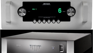
Audio Research Reference 1 preamplifier & VT200 power amplifier Measurements, Audio Research Reference 1
Sidebar 3: Measurements, Audio Research Reference 1
Unless otherwise noted, the measurements presented are for balanced operation. The Reference 1's output impedance at its line output measured 456 ohms (266 ohms unbalanced) in the left channel, maximum gain, with only slight variations between channels and at various level-control settings. The line-level input impedance measured 237k ohms (113k ohms unbalanced) in the left channel, maximum gain, dropping to 215k ohms in the right channel at maximum gain and rising to 261k ohms in the left channel at a low (9:00) level-control setting. Some of these variations are due to the sensitivity of the measurements to very small changes in the voltage readings at such high values of input impedance. Suffice it to say that the Reference 1's input impedance should have no effect on system performance. The output impedance at the tape output is 50 ohms with a 50 ohm source impedance and 595 ohms with a 600 ohm source impedance, indicating that the tape outputs are not buffered.
DC offset at the Reference 1's outputs measured a low 0.2mV in both channels. The preamp is noninverting from its line inputs to its main outputs in the unbalanced mode; in the balanced mode, pin 2 is wired as positive. Line-stage gain (CD input to line output) is 18.3dB balanced and 12.3dB unbalanced. The signal/noise ratio (ref. 1V) measured 86.2dB unweighted over a bandwidth of 22Hz–22kHz, 75.3dB unweighted from 10Hz to 500kHz, and 91.2dB A-weighted.
The Reference 1's frequency response is shown in fig.1. There are small variations in the high-frequency response with changes in the level-control setting, with the maximum deviation (-1dB at 20kHz) at a level-control setting of 3:00 plus one step. Unity gain occurs at 12:00+1. The volume-control tracking is excellent.
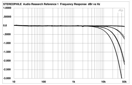
Fig.1 Audio Research Reference One, frequency response at 1V into 8 ohms, with volume control at (from top to bottom): maximum, 9:00, 12:00+1 step (unity gain), and 3:00+1 step (0.5dB/vertical div., right channel dashed).
The preamplifier's crosstalk, shown in fig.2, increases with frequency in the normally expected manner. The balanced crosstalk is lower, but the absolute separation is high enough in either case to be of no practical concern. The input voltages used here were high enough—290mV balanced and 300mV unbalanced—to keep the effect of noise on the readings to a minimum.

Fig.2 Audio Research Reference One, crosstalk (from top to bottom): L-R, R-L, unbalanced; R-L, L-R (balanced) (10dB/vertical div.).
The Reference 1's THD+noise plotted against frequency, referenced to these same input levels, is shown in fig.3—a very good result. Fig.4 shows the THD+noise percentage plotted against output voltage at 1kHz. The minimum points in the curves, just before the distortion increases rapidly, are the output values that were used for the measurements plotted in figs.2 and 3. Like most tube preamplifiers, the Reference 1 is capable of very high voltage output—far higher than you'll actually ever use—particularly in its balanced mode.
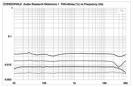
Fig.3 Audio Research Reference One, THD+noise vs frequency at 1V into 100k ohms: unbalanced (top) and balanced (bottom) (right channel dashed).

Fig.4 Audio Research Reference One, distortion (%) vs output voltage into 100k ohms: unbalanced (top) and balanced (bottom).
The spectrum of the Reference 1's output, reproducing a 50Hz input at a very high output level of 10V is shown in fig.5. The distortion here is very low; the second harmonic is the largest component, at 100Hz (just slightly greater than -70dB, or 0.03%).—Thomas J. Norton
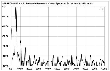
Fig.5 Audio Research Reference One, output spectrum, DC-1kHz, 50Hz at 10V into 100k ohms (linear frequency scale).
|
| ||||||||||
- Log in or register to post comments


| Loudspeakers Amplification Digital Sources | Analog Sources Accessories Featured | Music Columns Retired Columns | Show Reports | Features Latest News Community | Resources Subscriptions |
 © 2024 Stereophile
AVTech Media Americas Inc., USA
All rights reserved

