| Columns Retired Columns & Blogs |
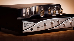
Artemis Labs PH-1 phono preamplifier Measurements
Sidebar 3: Measurements
Measuring the performance of phono preamplifiers can always be problematic because a signal generator is not a phono cartridge. Even with the wide variety of grounding options offered by my Audio Precision System One measuring rig—its generator outputs and analyzer inputs can be independently grounded or floated—as well as the options of grounding or floating the AC lead of the device under test, or running a separate ground lead from the unit's chassis to the analyzer chassis, the occasional component refuses to cooperate. Such was the case with the Artemis PH-1: no matter what I tried, I couldn't eliminate from its output a relatively high level of 120Hz hum.
The solution turned out to be to measure only one channel at a time. Connecting the grounds of the two input jacks, as would be the case when I tried to measure both channels simultaneously, was what had introduced the hum. This might be an issue in practical use only if the user tried to use a step-up transformer upstream of the PH-1, but I note AD had no such problems with his Tamura.
The voltage gain of 55.8dB, measured into our standard 100k ohms, was significantly higher than the 40dB typical of a moving-magnet phono preamp. As AD found, the PH-1 has sufficiently high gain to be used with some low-output moving-coil cartridges. But also as AD noted, the PH-1 inverts signal polarity. With no loading resistors inserted into the rear-panel ZIF socket, the input impedance was close to 46k ohms in the bass and midrange, this dropping inconsequentially to 32k ohms at 20kHz. As is to be expected from a tube design that dispenses with the usual cathode-follower stage in its output circuit, the PH-1's output impedance was fairly high, at 1k ohm in the midrange and treble, this doubling to 2033 ohms at 20Hz. This would roll off the bass into very low impedances, but as its user's manual warns, the PH-1 should not be used into loads below 12k ohms.
The preamp's RIAA error is shown in fig.1. The response meets tight ±0.1dB limits within the audioband, and is sensibly arranged to roll off above 20kHz, reaching –3dB around 70kHz. The two channels can also be seen from this graph to be closely matched in gain and frequency response. Measuring channel separation was problematic because of the aforementioned hum problem when both input jacks were connected to the analyzer. However, once I had solved that problem, it was good, at around 75dB in the midband.

Fig.1 Artemis PH-1, RIAA error (right channel dashed, 0.5dB/vertical div.).
The noise floor was quite low for a high-gain tube design. With shorting plugs inserted into the input jacks, the wideband, unweighted signal/noise ratios were 63.3dB left and 59.7dB right, both improving to 75.5dB when A-weighted. (All figures ref. 5mV input at 1kHz.) The maximum output level at 1kHz was very high, at 43.5V into 100k ohms and even 17.6V into 10k ohms. Overload margins were generally excellent, at 23.3dB at 1kHz and 25.5dB at 20Hz. (The latter corresponds to the 1% THD level in the PH-1's output not being reached until the level was an enormous 53V!) However, the overload margin at 20kHz was 12.2dB, which might be insufficient with some high-output MM cartridges.
Because of the PH-1's grounding incompatibility with my analyzer, I measured its left channel only when I examined how the THD+noise percentage changed with frequency. At low input levels, the THD+N into 100k ohms was below 0.1%, and even increasing the input signal to a high 15mV at 1kHz didn't result in much of a rise at midrange and low frequencies (fig.2, bottom trace). However, decreasing the load to 10k ohms, just below the minimum recommended, increased the midband THD to levels that might be just audible (fig.2, top trace). Perhaps more important, the THD into both loads increases above 4kHz, presumably due to decreasing gain margin in this region reducing the linearizing effect of negative feedback.

Fig.2 Artemis PH-1, left-channel THD+N (%)vs frequency at 15mV input at 1kHz into: 100k ohms (bottom), 10k ohms (top).
As always, what matters more than the absolute level of distortion is its harmonic makeup. Fig.3 shows the spectrum of the PH-1's output as it drove a 1kHz tone at 1V (equivalent to 1.4mV input) into 8k ohms. This is lower than Artemis' recommended load; even so, the THD is a low 0.068%, with the subjectively innocuous second harmonic the highest in level at –63.3dB. Note how the noise floor slopes down from left to right in this graph, a result of the RIAA equalization.

Fig.3 Artemis PH-1, spectrum of 1kHz sinewave, DC–1kHz, at 1V into 8k ohms (linear frequency scale).
The situation regarding high-frequency intermodulation was less rosy. With the preamp driving an equal mix of 19kHz and 20kHz tones into 8k ohms, the second-order difference components at 1kHz lay at a disappointing –43dB (0.73%, fig.4). Again, this suggests that high-output MM cartridges should not be used with the PH-1.

Fig.4 Artemis PH-1, HF intermodulation spectrum, DC–24kHz, 19+20kHz at 1V into 8k ohms (linear frequency scale).
Overall, the Artemis PH-1 offers good measured performance, though its high gain and limited linearity at high frequencies make it much more suitable for low-output MM or moderately high-output MC cartridges than for the "hottest" MM designs.—John Atkinson
- Log in or register to post comments
