Arc Angles: Optimizing Tonearm Geometry Page 5

Readers of a mathematical bent will already see what's wrong with this type of protractor. Correct arm/cartridge alignment requires that two independent parameters, overhang and offset, both be set correctly. As is drummed into math students when they learn simultaneous equations, to solve for two independent variables, you need two independent equations in those variables—or, in the case of an alignment protractor, you need two setting points. So achieving optimum alignment with a single-point protractor is a matter of luck. The only thing in its favor, apart from its simplicity, is that it tends to produce errors in overhang and offset that are of the complementary type; ie, if overhang is set too long, then offset is likely to be set too large, and vice versa.

Far better is the two-point protractor (fig.9). Usually, this exploits the fact that there are two zero-tracking-error radii across the disc, and that these are independent of arm length. The latter factor is vital, as it makes the two-point protractor a universal device. In use, the stylus is placed first at one zero-tracking-error radius, then the other, and the overhang and offset adjusted systematically until the cartridge sides align with the setting lines at both points. It is fiddlier than the single-point protractor and requires a little thought from its user, but it has at least the potential for setting both overhang and offset at their optimum values.

Of course, this assumes that the two zero-tracking-error radii are correctly chosen, which often is not the case. If you have a two-point protractor, check them carefully with an accurate ruler. For a modulated-groove-radius range of 56–146.3mm, they should be at 61.6 and 118.4mm; or, for 58–146.3mm, at 63.6 and 119.6mm. If you don't have a two-point protractor, or you do but it has the wrong zero-tracking-error radii, a Windows utility called ArmGeometer, available from the freeware page of my website, will draw a two-point protractor for you, and perform other alignment calculations besides.

The two-point alignment protractor is an excellent device—or would be if only it were easier to set cartridge offset more accurately than is generally the case. Many pickup arms' headshells obscure the cartridge sides, and we have even been regaled on occasions with cartridges having nonstraight, nonparallel sides, and even circular cross sections. As a result, accurately setting the offset is usually the biggest challenge in achieving optimum alignment.

Decades ago, I suggested a simple solution that fell on deaf ears. If I ruled the world, every pickup cartridge would be supplied with a simple, lightweight, clip-on device that, while allowing the stylus to be placed accurately on an alignment protractor, would project long straight edges, parallel to the cartridge front-back axis, to either side of the headshell, where they could be easily checked against long setting lines. If widely adopted, this one innovation would do more for the cause of accurate arm/cartridge alignment than a whole host of costly aftermarket alignment tools, which, whatever their accuracy (an issue I don't intend to get into), will only ever be deployed by a minority of LP users.

Of course, we depend in all this on the generator mechanism within the cartridge being very accurately aligned within the cartridge body—but then, all alignment devices presume that. Whether this trusting assumption is justified is not something I have ever seen investigated, and it wouldn't be an easy job. But the findings would make very interesting reading.

The surest way to achieve accurate arm/cartridge alignment would be to measure cartridge second-harmonic distortion vs groove radius. Curve-fitting software could then analyze the result and specify the required overhang and offset adjustments. This wouldn't just require special software: a special test disc would also be necessary, with an assurance that it had been cut with a meticulously aligned cutting head. Although software is available (Adjust+ from www.adjustplus.de) that assists cartridge-azimuth alignment and has various other features, it doesn't help with overhang and offset adjustment. Even if you'd be prepared to go to all this trouble, don't hold your breath.

Optimal or Not?
In all that has gone before, we have assumed that the Löfgren-Baerwald approach of minimizing the maximum LTE distortion across the modulated extent of the groove is indeed the optimal one. But there is good reason to suppose that it isn't, because lateral-tracking-error distortion is only one form of distortion afflicting vinyl-disc replay. Another source of distortion is tracing error, caused by the replay stylus being unable to follow the same path through the groove as the cutting stylus. In large part this is a function of the shape of the replay stylus, and depends critically on groove curvature. Because of this, tracing distortion worsens toward the end of a record side, as the waveform cut into the disc bunches up.

Although tracking-error and tracing-error distortions are different, there is clearly a case for supposing that, as tracing error increases toward the end of the side, tracking error should decrease. In this case, the optimal arm/cartridge alignment might be one that results in a distortion-vs-groove-radius curve like that in fig.10. But as tracing error differs according to stylus type, this approach also suggests that arm/cartridge alignment should vary accordingly, with a bigger disparity from the conventional alignment for a conical stylus than a line-contact stylus. The concept of a single "right" alignment would then be redundant.

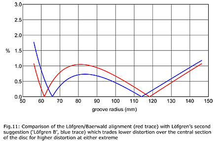
I'm not aware of anyone having experimented with this approach, but if someone out there has, I'd be very interested to hear of their findings. As already alluded to, Löfgren suggested an alternative alignment in his 1938 paper, which Dennes calls Löfgren B, but its raison d'être is different. It gives the result shown in fig.11, from which you can see that it lowers distortion over the middle portion of the disc at the expense of higher distortion toward either groove extreme, particularly the end of the disc side—an approach that just doesn't make sense to me.

But I expect Löfgren would be amused to know that, more than 70 years after the publication of his paper, we still agonize over this issue.

COMMENTS
scho2684's picture

Hi there,
Thanks for this very interesting explanation.

There are 2 things though:
It is stated that it would be good to have a alignment tool delivered with cartridges that obviously is referring to the cartridge body:

I have found that cantilevers and styluses are never 100% aligned correctly, so how to deal with this?

The other thing is the Lofgren B method on which you comment that the approach does not make sense to you because of, as I read it, the higher distortion at the end of the disc.

If I look at my records, most of them don't have modulated grooves there where Lofgren B is exceeding the distortion of the max mid area distortion of the Bearwald, so therefore I think that Lofgren B is the better one...(for me at least)

X