Arc Angles: Optimizing Tonearm Geometry Page 4

I still believe that 58mm is a good practical figure to use, but for the reason already stated, there is good justification for playing safe and using the theoretical minimum of 56mm—as I have done throughout this article.

Alignment Errors
Although this issue is often conveniently ignored, accurate cartridge alignment is very difficult to achieve, not least because the overhang and offset have to be set within extremely tight tolerances if anything like the distortion behavior shown in the red trace of fig.3 is to be realized in practice.

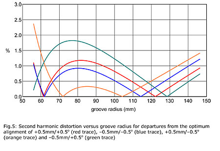
Let's demonstrate this by assuming that we can achieve accuracies of ±0.5mm in overhang and ±0.5° in offset—tolerances that are extremely difficult to achieve in practice, particularly the latter. Fig.5 illustrates the variability in distortion vs groove radius behavior encompassed by this error range by plotting the results for the four combinations of maximum error: +0.5mm/+0.5°, –0.5mm/–0.5°, +0.5mm/–0.5°, and –0.5mm/+0.5°.

As the plots show, you can strike lucky. If both errors are in the same direction (+0.5mm/+0.5° or –0.5mm/–0.5°, red and blue traces, respectively), then their effects are almost complementary and the result is acceptably close to the optimum. But if the errors are in opposite directions (+0.5mm/–0.5° or –0.5mm/+0.5°, orange and green traces, respectively), then the results are very much worse. The point, of course, is that you don't get to choose: If your tolerances are ?0.5mm and ?0.5°, you are as likely to suffer a bad result as a good one.

The message to take away from this is a stark one: accurate arm/cartridge alignment is a high-precision process. Achieving distortion behavior close to optimal in practice is no trivial task.

Arm Length
Because increasing the effective length of the pickup arm reduces the curvature of the arc through which the stylus traverses the record, an optimally aligned 12" arm generates less LTE distortion than an optimally aligned 9" alternative. This is why 12" arms were traditionally favored for professional disc-transcription purposes.

But because the optimum overhang and offset are both smaller for a 12" arm, a given misalignment will have a larger effect. So let's repeat the exercise above and see what transpires with alignment tolerances of ?0.5mm and ?0.5° in the case of a longer arm. For an arm of 305mm effective length, the optimum alignment requires an overhang of 12.19mm and an offset of 17.15° (compared to 16.43mm and 23.02° for a 230mm arm), and gives the distortion plot shown in red in fig.6, with the equivalent for a 230mm arm (ie, the red trace from fig.3) shown in light blue for comparison. The additional 75mm of effective length has cut the peak second-harmonic distortion (at 10cm/s RMS recorded velocity) from 1.07% to 0.78%, a reduction of 27.5%. So far, so good.

Fig.7 shows the effect on the 305mm arm's distortion plot of misalignments of +0.5mm/–0.5° and –0.5mm/+0.5° (red and blue traces, respectively), again with the 230mm equivalents in the background for comparison (footnote 16). If we take the maximum distortion in each case, the results are as in Table 1. From these we can see that, in the +0.5mm/–0.5° case, the 305mm arm's improvement in peak distortion decreases to 13%, and in the –0.5mm/+0.5° case to 15%. If we increase the alignment tolerance to ?1.0mm and ?1.0°, then the 305mm arm's advantage is reversed in the +1.0mm/–1.0° case, and cut to 9% in the –1.0mm/+1.0° case—so honors are now about even with a 230mm arm on the basis of maximum distortion.

Table 1

MisalignmentMaximum Distortion (%)
230mm arm 305mm arm
+0.5mm/–0.5° 2.362.06
–0.5mm/+0.5° 1.821.55
+1.0mm/–1.0° 3.073.35
–1.0mm/+1.0° 2.652.41

Whether a 12" arm's improvement in LTED is worth its higher effective mass, and reduced bending and torsional stiffness, has always been a judgment call. What these figures show is that unless a 12" arm is very carefully aligned, even that advantage can easily be squandered.

Alignment Protractors
Arm/cartridge alignment is traditionally set using an alignment protractor. The terminology doesn't strike me as quite appropriate, but there we are: it's set in stone. Human ingenuity being what it is, numerous different designs of alignment protractor and other alignment tools have appeared down the years, some of them demonstrating a profound misunderstanding of the problem at hand. I won't attempt a history or taxonomy of them here; instead, I'll quickly describe the two that you're most likely to encounter, as they are commonly supplied by pickup-arm manufacturers.

The first, the single-point protractor (fig.8), used to enjoy a hegemony. It was an oft-repeated (and misleading) mantra of the 1960s and 1970s that "lateral tracking error should be zero at the innermost groove," and so the one-point protractor typically placed the stylus at the supposed innermost modulated groove radius (often 60.375mm) and incorporated setting lines to which the cartridge sides should be aligned.


Footnote 16: You may notice in these graphs that all four traces cross at the zero-tracking-error radii for the optimum alignment—an intriguing property that I've noticed for the first time here and can't yet explain.
ARTICLE CONTENTS

COMMENTS
scho2684's picture

Hi there,
Thanks for this very interesting explanation.

There are 2 things though:
It is stated that it would be good to have a alignment tool delivered with cartridges that obviously is referring to the cartridge body:

I have found that cantilevers and styluses are never 100% aligned correctly, so how to deal with this?

The other thing is the Lofgren B method on which you comment that the approach does not make sense to you because of, as I read it, the higher distortion at the end of the disc.

If I look at my records, most of them don't have modulated grooves there where Lofgren B is exceeding the distortion of the max mid area distortion of the Bearwald, so therefore I think that Lofgren B is the better one...(for me at least)
X