Arc Angles: Optimizing Tonearm Geometry Page 2

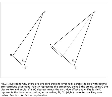
The latter feature is necessary to achieve the first, but I know from three decades of writing on this subject (footnote 9) that it puzzles many people. So, using some straightforward geometry, let's clarify how it comes about. Fig.2a shows a triangle representing a pickup arm aligned at the inner of the two zero-tracking-error radii (distance SC). Point S represents the stylus position, point P the arm pivot, and point C the center of the turntable platter. The distance SP is the effective length of the arm and exceeds the distance CP by the overhang: if we use the figures quoted in the last paragraph, then Wilson's equations give this to be 18.56mm. Angle "a" is 90° minus the cartridge offset angle (24.63° from Wilson's equations), and so the line SC is along a radius of the disc and the cartridge front-back axis is at a tangent to the groove. If we now extend the line SC beyond C and rotate PC about P, we find that there is a second triangle (fig.2b) where the same conditions are met, and the tracking error is therefore again zero. Thus there are two zero-tracking-error radii, and distance SC now represents the outer of them.

Where Wilson went wrong in his analysis was to assume that the distortion caused by LTE is proportional only to LTE itself. In fact there is another vital parameter, namely linear groove speed (that is, the speed at which the groove passes the stylus), which varies by a factor of about 2.5x from the outermost to innermost modulated groove radius of an LP. LTED, it turns out, is inversely proportional to linear groove speed, and so the same LTE at the innermost modulated groove radius of an LP will result in about 2.5? higher distortion than the same angular error at the outermost modulated groove radius.

As we now know, the first person to realize this and correct Wilson's equations was Erik Löfgren. But in the late 1970s, when headlines about arm geometry began to appear in the audio press, this breakthrough was still accredited to Baerwald, and therein lies a tale. For reasons that puzzle me to this day, Baerwald decided to publish in his paper an approximate equation for optimum overhang that many people subsequently used, assuming it to be sufficiently accurate. In fact, it isn't, as fig.3 illustrates. This time, the graph plots distortion vs groove radius (exactly what distortion I'll describe shortly), the red trace showing the proper, non-approximated Baerwald alignment, and the blue trace the alignment with Baerwald's approximated overhang. Again, this is for a 230mm arm across the groove dimensions already given.

The shape of the red trace is reminiscent of that in fig.1, and shares the same key features: there are two zero-tracking-error radii and three equal maxima. What has changed is the positioning of the zero-tracking-error radii, now at 61.6 and 118.4mm, both of which have migrated toward the innermost recorded groove radius in order to "weight" the LTE appropriately across the disc to give the three points of equal maximum distortion. The blue trace is obviously in error, caused by Baerwald's approximate overhang being 15.84mm when the correct figure is 16.43mm.

Bear this in mind if you read some of the material published on arm alignment in the late 1970s and early 1980s, as some authors quoted overhang figures calculated using the approximate equation. When writing on this subject three decades ago, I took to referring to the "self-consistent" Baerwald alignment to indicate that the non-approximated overhang was used. Now I know that it deserved to be called the Löfgren alignment all along, or "Löfgren A," as Dennes refers to it—Löfgren also offered a second option, more of which later.

Now we know what the distortion characteristic of an "optimally aligned" arm-cartridge combination should look like: the red trace of fig.3. But this just prompts a series of secondary questions: How are we to achieve this alignment? What are the effects of alignment inaccuracies? What minimum and maximum modulated groove radii should we use? Is a 12" effective-length arm really superior to a 9" one in this respect? Is this alignment truly optimal? Is LTED audible, or are we getting our underwear in a bind over nothing here?

Audibility
Let's tackle that last issue first, since the answer to it justifies all that follows. And let's begin by clarifying what nature of distortion LTE produces, and what exactly is plotted on the vertical axis of fig.3.

As Löfgren and Baerwald both demonstrated, the largest nonlinearity resulting from LTE is second-order, which on a pure-tone signal gives rise to second harmonic distortion. This is what is plotted in fig.3, and in all the other graphs of LTED vs groove radius that I have ever seen. Higher-order harmonics are also produced, but at progressively lower levels. The amount of distortion depends not only on LTE (footnote 10) and linear groove speed but, as usual, also on signal amplitude, represented in the distortion equation by recorded velocity. Because of this, all graphs like fig.3 should state exactly what recorded velocity is assumed. A figure of 10cm/s Root Mean Square (RMS) is commonly adopted, and applies to all graphs of distortion vs groove radius in this article. This represents a moderately high recording level, but bear in mind that when, in the 1970s, Shure Brothers measured recorded velocities from commercial recordings, they found peak figures in excess of 80cm/s, equivalent to over 57cm/s RMS—not that any cartridge could track that. The relative level of second harmonic distortion is proportional to recorded velocity, so 1% second harmonic at 10cm/s becomes 4% at 40cm/s—but most cartridges will be mistracking before that level. On complex signals such as music, LTE distortion introduces intermodulation components as well as harmonic ones and, as I've described before in these pages (footnote 11), these are likely to be much more audibly significant.


Footnote 9: A collection of some of the articles I wrote about arm/cartridge alignment for Hi-Fi Answers and Practical Hi-Fi, beginning in 1978, can be found on my website.

Footnote 10: Strictly, the distortion depends on tan(theta), where ? is the LTE, but for small values of theta the approximation theta=tan(theta) is sufficiently accurate. Note that this requires theta to be in radians, not degrees.

Footnote 11: K. Howard, "Euphonic Distortion: Naughty but Nice?," Stereophile, April 2006, Vol.29 No.4.

ARTICLE CONTENTS

COMMENTS
scho2684's picture

Hi there,
Thanks for this very interesting explanation.

There are 2 things though:
It is stated that it would be good to have a alignment tool delivered with cartridges that obviously is referring to the cartridge body:

I have found that cantilevers and styluses are never 100% aligned correctly, so how to deal with this?

The other thing is the Lofgren B method on which you comment that the approach does not make sense to you because of, as I read it, the higher distortion at the end of the disc.

If I look at my records, most of them don't have modulated grooves there where Lofgren B is exceeding the distortion of the max mid area distortion of the Bearwald, so therefore I think that Lofgren B is the better one...(for me at least)
X