| Columns Retired Columns & Blogs |
Measuring Loudspeakers, Part Two
This series of articles was initially written (in slightly different form), as a paper presented at the 103rd Audio Engineering Society Convention, New York, September 1997. The preprint, "Loudspeakers: What Measurements Can Tell Us—And What They Can't Tell Us!," AES Preprint 4608, is available from the AES, 60 East 42nd Street, Room 2520, New York, NY 10165-0075. The AES internet site, www.aes.org , offers a secure transaction page for credit-card orders.
In the first part of this series of articles, I examined why I feel a review magazine should include measurements in its loudspeaker reviews. I also went into some detail on the concepts of electrical impedance and voltage sensitivity and what they mean to audiophiles. Now it's time to turn to the basics of a speaker's acoustic behavior.
Impulse & Step Responses
Before the days of digital storage oscilloscopes, it was difficult to examine the time-domain behavior of loudspeakers. Capturing the time record of a component's output is almost trivially easy these days, however. This puts a powerful tool in the hands of audio engineers—and even audio reviewers!
The fundamental test signal in the time domain is the impulse response—the output of the component when presented with a narrow rectangular voltage pulse—which carries within it a complete characterization of a component's linear performance. However, there are practical difficulties with using pulses to test loudspeakers—the very high dynamic range leads to a compromised Signal/Noise Ratio—so I use a method based on Maximum-Length Sequence test signals [29], realized in a commercial piece of test equipment, the MLSSA measuring system from DRA Labs [30].
MLSSA feeds the loudspeaker a pseudo-random sequence of rectangular voltage pulses. By performing a cross-correlation function between the test signal and the signal picked up by a microphone, the host PC can calculate the system's impulse response. It is important to remember that this is the calculated impulse response, not the response of the speaker-under-test to an electrical impulse. As pointed out to me in 1991 in a private communication by Verity's Graham Bank, then with Celestion, the two are not the same. The loudspeaker might well behave differently when presented with the low-dynamic-range MLS pulse train than it would when driven by a high-dynamic-range single impulse. The assumption is also made that a linear system is being tested and that is not necessarily the case. The presence of nonlinear behavior in the loudspeaker being tested leads to spurious "echoes" or reflections in the calculated impulse response [31].
Fig.8 shows a perfect impulse response. The voltage instantaneously rises from the graph's time axis, remains at a fixed DC level for a small period of time, then instantaneously drops back to the time axis. The width of this rectangular pulse is inversely proportional to the frequency bandwidth of the signal. If the impulse were infinitely narrow on this graph's time axis, it would require a system with infinite bandwidth—"from DC to light," was how one of my college professors used to describe it—to be reproduced with its shape intact.
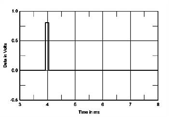
Fig.8 Perfect impulse response.
NEXT: Page 2 »
|
| |||||||||
- Log in or register to post comments


| Loudspeakers Amplification Digital Sources | Analog Sources Accessories Featured | Music Columns Retired Columns | Show Reports | Features Latest News Community | Resources Subscriptions |
 © 2024 Stereophile
AVTech Media Americas Inc., USA
All rights reserved

